Computerman29
Full Member level 3

- Joined
- Jul 23, 2006
- Messages
- 166
- Helped
- 21
- Reputation
- 42
- Reaction score
- 18
- Trophy points
- 1,298
- Location
- North Judson, IN USA
- Activity points
- 2,789
pickit vpp voltage level error
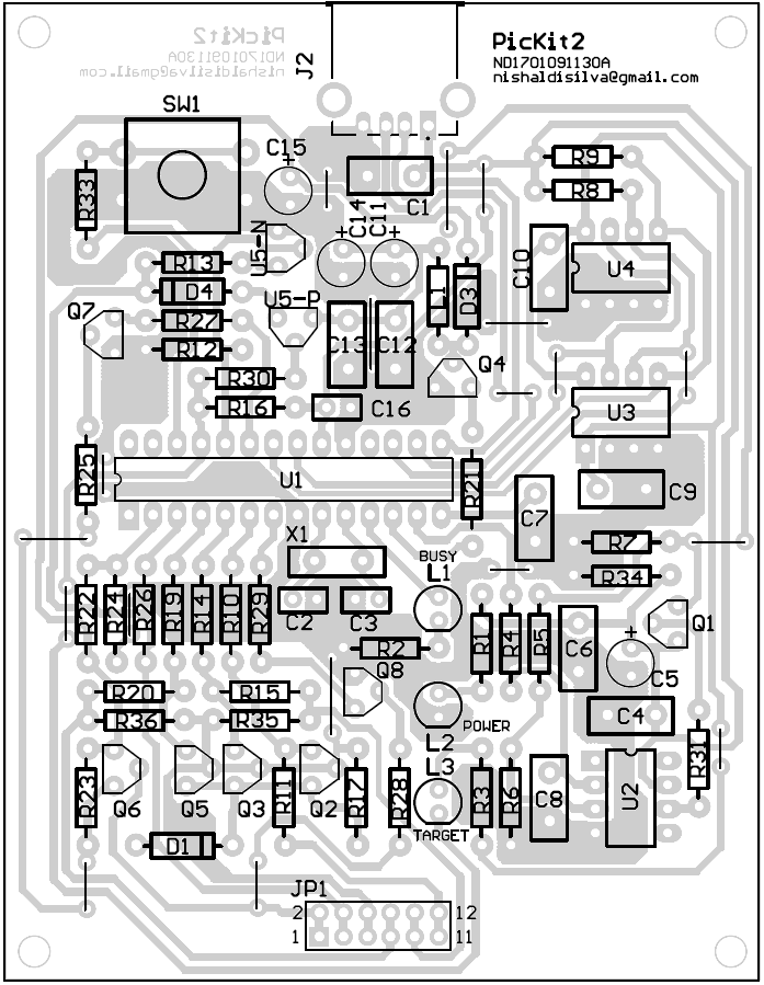
This circuit is the original PicKit 2 done in TH. It needs no modification to program without PC.
Don't know, but looks good.
Do not use 741. The op-amp needs to be a CMOS rail to rail I/O.
For the voltage errors, check the transistors, MOSFET's, diodes, and IC's. Make sure they are properly inserted.
You are correct. It would have been much less hassle and only a few more dollars to just buy an original, but as I have said in other posts, some people (like myself) just like to build things!
Exchange the parts in Eagle (schematic), then modify the layout (in Eagle), and they will work nicely. The layout could be dramatically improved anyway.
One more thing:
Don't forget to solder a .1uF ceramic cap between the power pins of the PIC. An 0805 surface-mount on the bottom of the board is best.
By the way, can some one modify this circuit to programing with out PC? Thanks!
This circuit is the original PicKit 2 done in TH. It needs no modification to program without PC.
IRF9610 (P-Channel [TO 220 package]) instead of BS250
Don't know, but looks good.
opamp 741 instead of MCP6271
Do not use 741. The op-amp needs to be a CMOS rail to rail I/O.
For the voltage errors, check the transistors, MOSFET's, diodes, and IC's. Make sure they are properly inserted.
I assume that, these guys/gals are making it not for using alone but for a feel of realizing a project (proven) in its totality, with their local means.
You are correct. It would have been much less hassle and only a few more dollars to just buy an original, but as I have said in other posts, some people (like myself) just like to build things!
I think the NTD3055L can't be replace by 2N7000 & NTD20P06L can't replace by BS250 as the lead are difference.
Exchange the parts in Eagle (schematic), then modify the layout (in Eagle), and they will work nicely. The layout could be dramatically improved anyway.
One more thing:
Don't forget to solder a .1uF ceramic cap between the power pins of the PIC. An 0805 surface-mount on the bottom of the board is best.


