Continue to Site

Welcome to EDAboard.com

Welcome to our site! EDAboard.com is an international Electronics Discussion Forum focused on EDA software, circuits, schematics, books, theory, papers, asic, pld, 8051, DSP, Network, RF, Analog Design, PCB, Service Manuals... and a whole lot more! To participate you need to register. Registration is free. Click here to register now.

Sinewave inverter prototype...

Status
Not open for further replies.
change the totem pole with uc3842/3 from scheme #324?
possible try such change with STM8, but in scheme with ATMega8 some part of dead-times is formed by means of transistor inertias so can be not. And for UC3842 the uvlo tresholds is 16V_on/10V_off (8,5/7,9V for 3843).

can 3842 drive more than 1 fets?
this depends from fet gate charge and required switching speed.
 

IRF3205 is around 150nC gate charge so may be one or two fets per 3842.
but this microcircuit is comparable on price with cheap mosfet and possible to put it with 1:1 proportions.
 

not so much important frequencies but how much time of the switching. if time of the switching will beside 300 nanoseconds the UC3842 is handle 3 75N75 mosfets, 500ns - five and so on. For UC3842 microcircuit it is necessary not to exceed pulsed current 1А and average 200mA.
 

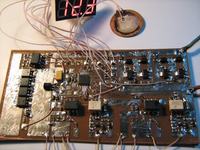
Worked version of converter already mentioned at message #378.
Tested only with small ACIM load.
 

Attachments

  • c hex pcb schm _ fbus_pplf swi.rar
    145.2 KB · Views: 225

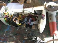
final version. tested with "Kress WS710" angle grinder.

i think it is possible to double output power
 

Attachments

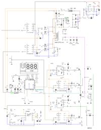
  • hex_v2.zip
    8.3 KB · Views: 169
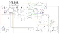
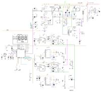
  • schm1200VA.gif
    schm1200VA.gif
    138.5 KB · Views: 265

Congratulations on a very nice and challenging project. :thumbsup: :thumbsup:

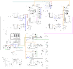
I have a question: what schematic drawing program did you use? It looks very nice, and I specially like the fact that you can color-code the signals. It makes the schematic much easier to follow.
 

apropos - a 1,5kW project with switchable (depends on load) DC_DC channels in step_up stage. not ready yet )
 

i shared an external link in my post #398 and im warned, there you need registration.
sorry for that, here is my sch and idea but i realized that its possible only with HV PWM.
First boosting the voltage to 220-30-440-60 and then PWM that to 50Hz. :)
sch.PNG
the ic used is tl494 and the mosfet driver is ir2111
 

Status
Not open for further replies.

Similar threads

Part and Inventory Search

Welcome to EDABoard.com

Sponsor

Back
Top