Continue to Site

Welcome to EDAboard.com

Welcome to our site! EDAboard.com is an international Electronics Discussion Forum focused on EDA software, circuits, schematics, books, theory, papers, asic, pld, 8051, DSP, Network, RF, Analog Design, PCB, Service Manuals... and a whole lot more! To participate you need to register. Registration is free. Click here to register now.

Sinewave inverter prototype...

Status
Not open for further replies.
Hi, DeepOne
I want to set up circuit # 88, but I do not have ir2109.
Among the available ones I have the: ir2110, ir2104, ir2101, ir2304 and ir2010
I can replace the ir2109 by which one.
For atmega8.
 

I do not have enough 50n03 should have been replaced by 50n06, but it broke down immediately after the power supply. Maybe, two different types of Mosfet parameters: Turn-on / off delay time, Rise / Fall Time. So 50n03 replaced by IRF3205 ok or not?
In diagram # 463, I want to raise the voltage to 48VDC or 24VDC, what is I need to change? I'm with appropriate transformer, 80N70, 50N06 .... The goal, increasing the capacity of 500-800w.
Thank you!
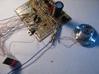
?nh 1.JPG
?nh 2.JPG
 

Hi, Thassio28.
i take a look at datasheet - ir2109 can be replaced with ir2104.

thwcs said:
In diagram # 463, I want to raise the voltage to 48VDC or 24VDC, what is I need to change? I'm with appropriate transformer, 80N70, 50N06 .... The goal, increasing the capacity of 500-800w.
power more than 300W and supply voltage >12V that is not good idea for circuit from message #463.
So 50n03 replaced by IRF3205 ok or not?
higher gate charge with IRF may be a small problem. anyway that is not a deal for it broke down immediately. in the same way either as turn-on/off delay time, rise/fall time.
 

Hello, DeepOne I did the circuit # 88 but I'm having some problems, the signal arrives until the IR but nothing comes out of it, just disconnecting the SD pin of the two ic, 2 leds turns on half wave.


The display is also not showing right, after turning on the circuit it counts every 5: 105a 110a 115a 120a and repeats.
 

just disconnecting the SD pin of the two ic, 2 leds turns on half wave
looks like mcu shut off inverter because voltage in power network is present. try to connect PC2 (in TQFP32 version) or PB5 (in DIP28) to Vcc.
after turning on the circuit it counts every 5: 105a 110a 115a 120a and repeats.
check button and LM358 output.
 

Hello, not to go unanswered, it seems that it was working, I just needed to connect to the transformer, but accidentally I caused a short one that ended up burning the IR, I bought another pair but the led was shorted and damaged again.
So I bought more drives and the STM8, ATTINY on ebay to try again and other circuits.
 

because this is slightly simple decision.
________________________________________
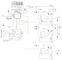
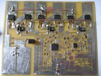
next prototype - 3 phase 50...400Hz DCAC converter, not tested

Dear DeepOne
This diagram, given the sine wave or the square wave? If I replace IRF3205 by IRF840, can I raise the voltage from 36VDC to 320VDC?
Do you have a version that uses Atmega8?
Thank you!
 

given the sine wave or the square wave?
sine wave with 31kHz spwm
If I replace IRF3205 by IRF840, can I raise the voltage from 36VDC to 320VDC?
no, that is unreliable without some changes in drivers and mcu program.
Do you have a version that uses Atmega8
no, Atmega8 is unbeseeming for this.
 

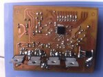
Hi DeepOne, after a long wait for parts I finally did circuit #423 with the IR2109 and it worked fine, I'm still waiting for parts to do with STM8.
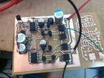
I leave here an image of the circuit board.
foto.jpg
 

Hello again,DeepOne.

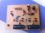
I have done the circuit # 221, 220v for 110v, but I am giving a problem as follows the images (1) with no load at the output (2) with a cooler connected at the output (3), (4) distortion occurring in the sixth pin of the second 6n137 with load, the rest of the circuit is ok.

You have any idea what could be wrong?

Tests performed between 12v and 30v.
(1)
1.png

(2)
ad.png

(3), (4)
ffhf.png
hff.png
 

Hello, Thassio28.
any idea what could be wrong
may be that is in consequence of pcb tracing, or influence of the hindrances on BKIN pin (PD1) or fault in 6N137 feeding - i do not know. this is aging scheme, requires some improvements.
 

220VAC_110VAC converter with some improvements. but mcu program tested only in model-based charge, not in real device.
 

Attachments

  • new_220_110.GIF
    new_220_110.GIF
    89.5 KB · Views: 496
  • 220_110_stm8.zip
    107.2 KB · Views: 269
Hi,
I started to build this last version but no signal, without input feedback the display shows the frequency and then LO.HV without pwm, with the feedback the display shows ocpt without pwm.
 

"LO.HV" says no high voltage or it is not enough for given output voltage, so mcu can not calculate PWM depth.
"ocpt" says mcu detect UC3843 overcurrent protection operated. to disable this function connect PORTB.7 and PORTB.6 to 5V.
 
Last edited:
Status
Not open for further replies.

Similar threads

Part and Inventory Search

Welcome to EDABoard.com

Sponsor

Back
Top