KhaledOsmani
Full Member level 6

1N400x across the relay COIL, not the terminal (switch) side. It can be any 1N400x or similar diode, the voltage rating is not important as it will never exceed ~0.7V when the diode conducts and the relay coil voltage when not conducting.
The 10W rating of the bleed resistors is far more than you need. What is more important is their voltage rating, most small resistors are rated no higher than 250V so it would be best to use two in series to share the voltage. The resistance isn't critical, it is only to ensure the capacitors discharge when out of circuit for safety reasons. Bear in mind that to charge them to peak voltage you would have to open the relay at the exact instant of the AC peak, the chances of that happening are fairly low and it is far more likely they will have a lower voltage across them. If you use two 100K 1W resistors in series it will be more than adequate and much cheaper/smaller.
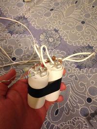
Yes, if you need large capacitor values, make it from several smaller value capacitors in parallel.
Brian.
Hello Brian, and thank you!
I've tested the system with the 60W fan, results were:
Vinput = 204VAC
Iload = 0.237Amps
Phase = 43
pf = 0.737
When pushed the red button, and according to the calculation I wrote in previous reply, I got at the end that to improve pf of 60W fan from 0.7 to 0.85 I need around 200uF capacitor.
This is the code:
Code:
capparameters:
switch_pressed = 0
realpower = x * allcurrent * pf
tan = Sin(phasedeg) / Cos(phasedeg)
qold = realpower * tan
Lcdcmdout LcdClear
Lcdout "Qold = ", #qold, "VAR"

phasedeg2 = 31.788 * 0.01745329
tan2 = Sin(phasedeg2) / Cos(phasedeg2)
tan3 = Sin(phasedeg - phasedeg2) / Cos(phasedeg - phasedeg2)
qnew = realpower * tan3
Lcdcmdout LcdLine2Home
Lcdout "Qnew = ", #qnew, "VAR"

reactance = x * x / qnew
Lcdcmdout LcdLine3Home
Lcdout "Xc= ", #reactance

capacitance = 1 / 2 * 3.1415926 * 50 * reactance
capacitance = capacitance * 0.00001
Lcdcmdout LcdLine4Home
Lcdout "C = ", #capacitance, "   uF"
WaitMs 1000

cap_measured = 1

activatecapbank:

If cap_measured = 1 And switch_pressed = 1 Then Goto capon
Lcdcmdout LcdClear
Lcdout "Press Red Button"
Lcdcmdout LcdLine2Home
Lcdout "To Continue"
WaitMs 1000

Lcdcmdout LcdClear
Lcdout "Qold = ", #qold, "VAR"
Lcdcmdout LcdLine2Home
Lcdout "Qnew = ", #qnew, "VAR"
Lcdcmdout LcdLine3Home
Lcdout "Xc= ", #reactance
Lcdcmdout LcdLine4Home
Lcdout "C = ", #capacitance, "   uF"
WaitMs 1000

Goto activatecapbank

Return

capon:
switch_pressed = 0
Lcdcmdout LcdClear
Lcdout "Activating cap:"
Lcdcmdout LcdLine2Home
Lcdout "C = ", #capacitance, "   uF"
Lcdcmdout LcdLine3Home
Lcdout "Vcap = 400VAC"
'High the port where cap is installed
Goto prog_end
Return
Is it logical to have a 200uF for a single phase 60W inductive fan?
Are there any solid switching circuits to drive the capacitor when needed rather than the open relay switch?!
Much thanks


