Continue to Site

Welcome to EDAboard.com

Welcome to our site! EDAboard.com is an international Electronics Discussion Forum focused on EDA software, circuits, schematics, books, theory, papers, asic, pld, 8051, DSP, Network, RF, Analog Design, PCB, Service Manuals... and a whole lot more! To participate you need to register. Registration is free. Click here to register now.

PIC controlling AC loads

Status
Not open for further replies.
can you tole me isit correct circuit for the heater coil control?
Please copy links correctly. The circuit is basically O.K. It uses a zero-crossing-detector triac. As I previously explained, you can use it with slow pwm control (e.g. 1 to 4 secs period) without synchronization to the AC voltage.
 
Hi

See this attachment.Also told me for the heater control i use zero crossing circuit or not.why?
 

Attachments

  • TRIAC_driver.jpg
    TRIAC_driver.jpg
    16.6 KB · Views: 399
Last edited:

I don't think it is your fault ;-) some URLs address only those who live on the planet Earth. :grin:

In any case, you can follow FvM advices though he might be lazy 'sometimes' to give you clearly all details :)

After I saw the schematic, I think all is already clear.
So I assume your mains is 120Vac.

Of course you can use MOC3041 or MOC3042, you would need to decrease the value of R26 only.

If your 5V supply is not weak you can just drive the optocoupler by a DC current when you like to turn on the heater then cut this current for off state. The power triac will turn on only at AC zero-crossings, actually after a short delay till the voltage on the triac is high enough to trigger the gate (via R18). The triggering current may differ from one triac to another (even from the same lot). But in worst case the load power won't be less than 99% of the full power (no triac).
 
Last edited:

Hi


In this circuit(#82) there is no zero crossing circuit mention.So i ask for heater control its required or not?In #76 you say without zero crossing we can control the heater.I know by zero crossing i am able to get exact firing angle but without zero crossing its also possible only not exactly.So i just want to know why i am going to use zero crossing or why i am not going to use the zero crossing circuit for the heater?Also told me if i am not using the zero crossing circuit then what happen and if i have go through it then what happen about my heater?

Thanks you
Nilesh
 

On the circuit (#82), MOC304x has its own zero crossing detector.

So your controller doesn't need another one, unless you like to be sure that the half cycles are turned always in pair in order to have a zero average current. But turning on sometimes (by using a random DC driving current) an odd number of cycles after many cycles will produce a temporary small DC average value.
 
Last edited:

Hi KerimF
I am going to use 230v AC main.But in programming to get the exact temperature i am using the PID controller.as per PID controller output it varies the PWM every time so i am confused.I have fired or only use the opto isolater when the PID output changes.Can i use without zero crossing just like show in #82 and controll through PWM?If moc304? had their own zero crossing then how the controller communicate with that means moc have only one connection of pwm which is given by controller then how the controller detect the zero crossing?
Thanks and regards
Nilesh
 

Sorry, what do you really mean by PWM?
If you mean its period is 10ms (as of the mains) then I don't use to call it PWM since it should be synchronized with the mains cycles (by a zero-cross detector for example). Then we try to delay the triggering pulse to have the effect of AC dimmer. The triggering pulse could be a short one (100us for example) or a long one (up to the end of the actual half cylcle, a bit shorter).
 

Hi KerimF

If the previous temperature and set temperature have some difference then as per pulse width modulation are changes the duty cycle and pass the sufficient current and achieve the set temperature.and also if the temperature decrees then again i it give some small gate triggering pulse to the temperature maintaining at the same level.I have controlled the duty cycle of the PWM.How i interface with the triac

In fig #82 can told where 3 and 5 are going to connect?They are the connections for PWM and zero crossing detectors?Then which connection is connected where?
 
Last edited:

If one terminal of the load is connected to the power Neutral then 5 should be connected to the hot line and 3 to the other terminal of the load.
Note: connecting 3 to the Hot line and 5 to the load works too since the load resistance is relatively much smaller than R18. Because in this case the gate limiting current would be the sum of R18 and the resistance of the load.
 
Last edited:

Hi
where we connect the 3x and 5x which is shown after r26.3x and 5x are the connection of the moc304x .Where we are given gate trigger because 5 v is given continuously to the moc 1.6 and 5 terminal of the moc is connected to the triac. from where controller got this is tthe zero crossing detector?I have attched my design please told me is it correct?
thank you
nilesh
pwm1.JPG
 
Last edited:

Are we talking of the same circuit?
on post #89:
3 refers to 3-CN1
5 refers to 5-CN1

Both 3-CN1 & 5-CN1 are electrically isolated from R26... right?
The pins of MOC are pin4 and pin6, on the side of the load (the power side), which are the terminals of its small triac. And the MOC pin1 and pin2 are on the side of the uC. It seems you couldn't download the datasheet of this MOC IC because the zero crossing detector is integrated inside it. So even a sufficient DC current flows in the LED input (between pin1 and pin2), the small opto triac will not turn on till the mains voltage become close to zero volt. That is why you will be free to drive the MOC at random (relative to mains cycles) while you are sure the load will be turned on at zero crossing only.

Note:
A professional engineer would try to adjust the time on to be always an interger number of full cycle time (here 20ms) so that the load will be on during an even number of half cycles. Otherwise the load would be on sometimes during an odd number of half cycles which results a small average DC current in the power line but this is not too important in your case :)

Edited:
I am referring to post #82 for the circuit, on yours most nodes have no label.
 
Last edited:

Hi KerimF

Thank you now i understand and also the schematic shown in #90 is it correct or required any necessary changes please told me.

thank for your help
Nilesh
 

It misses the limiting current resistor between the uC port and the MOC LED. Its value could be calculated:
R_led = (Vcc - V_led) / I_max
I_max = 15 mA for MOC3041
I_max = 10 mA for MOC3042
I_max = 5 mA for MOC3043

For example, for MOC3043
R_led = (5 - 1.3) / 0.005 = 740 Ohms => 680 Ohms as the nearest standard (E12) value.

About R13 (on you circuit) which is equal to 390 Ohms, it will determine when the power triac will be on after the zero crossing based on the formula:

Vrms*SQRT(2)*SIN(100*PI*t) = Rs*Ig + Vsat + Vg
Where:
Vrms = 220V for example (for the mains)
100 for 50 Hz
t = time delay after a zero crossing
Rs = the series limiting current resistor between MT2 and the opto triac (here it is 390 Ohms)
Ig = the minimum current that trigger the power triac
Vsat = the on voltage across the opto triac (it is about 2V more or less)
Vg = the drop between the power gate and MT1 (it is about 0.75 to 1 V)

This equation can be solved for t. As we see, t is longer if Vrms is lowered for example.
 
Last edited:

Hi
Thanks for your reply. i have use MSP430f2274 controller whose output voltage is 3.3-1.5 volt with the current 2 ma to 8 ma so i think 360 ohm is sufficient is it correct?
thank you
Nilesh
 
Last edited:

It is ok for 3.3V

Hmmm... but there might be a considerable drop on the uC port... you may need to lower the value 360 Ohms till you get:
V_resistor / R_resistor > 5 mA
You can test this without connecting anything on the other side of the MOC... assuming you will build the test circuit as real ;-)
 

Hi
uC give the output 2ma with 3.3 volt if i drawn 8ma current that time voltage is 1.2 volt so i consider for 5 ma near about 2 V and made the calculations and i find 140 ohm is sufficient.Is it working fine with this resister.

thank you
nilesh
 

I am not sure... I used to trust what I have in real after I build a circuit... so you can start with 140 Ohm but if its voltage is lower than 0.7 volt (on the board when the port is on), you will need to decrease it even more.
 
  • Like
Reactions: FvM

    FvM

    Points: 2
    Helpful Answer Positive Rating
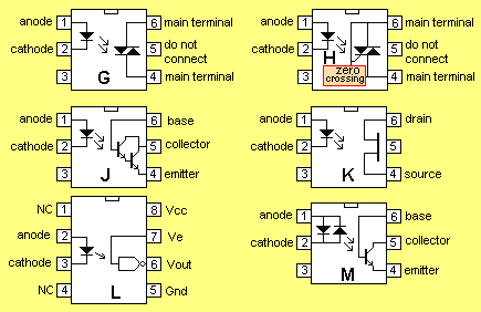
OptoCouplers-2.gif


Hi all i found a zero crossing optocoupler.
This is what in my mind and i want to ask you guys if it will work this way.

since we are using zero crossing optocoupler does it mean we dont need anymore to use a zero detection circuit?
 

Status
Not open for further replies.

Similar threads

Part and Inventory Search

Welcome to EDABoard.com

Sponsor

Back
Top