Continue to Site

Welcome to EDAboard.com

Welcome to our site! EDAboard.com is an international Electronics Discussion Forum focused on EDA software, circuits, schematics, books, theory, papers, asic, pld, 8051, DSP, Network, RF, Analog Design, PCB, Service Manuals... and a whole lot more! To participate you need to register. Registration is free. Click here to register now.

PIC controlling AC loads

Status
Not open for further replies.
Re: PIC complete discussion for all

Just a minor remark on the circuit shown on post #5.
The resistor R9 should be connected to pin 1 of the load triac.
That is all :)
Kerim

it will work either ways since triac is bidirectional device.. corect me if Im wrong..
 

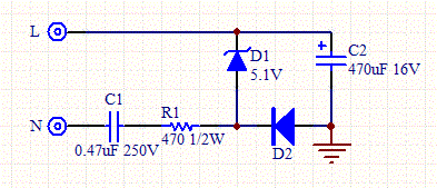
are you referring something like this?


Capacitive-AC-DC.gif

Yes. Something like this.

---------- Post added at 21:27 ---------- Previous post was at 21:24 ----------

it will work either ways since triac is bidirectional device.. corect me if Im wrong..
Take a look here:
38_1311175628.png


---------- Post added at 21:29 ---------- Previous post was at 21:27 ----------

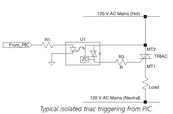
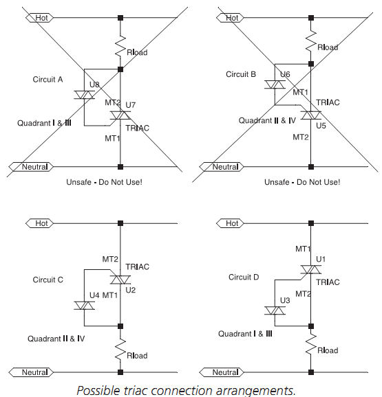
•฀ As฀ a฀ matter฀ of฀ safety,฀ circuits ฀A฀ and ฀B฀ are฀ unacceptable.฀Contrary฀ to฀ good฀ safety฀ practice,฀ when ฀the฀ triac฀
is฀ off,฀ both฀ sides฀ of ฀the ฀load฀ remain฀ connected฀ to฀ the฀ hot ฀side฀ of฀ the฀ 120฀V ฀supply฀ mains. ฀A฀switch,฀ such฀
as฀the฀triac,฀when฀ off฀ should฀ isolate฀ the฀ load฀ from ฀the฀ hot฀ side฀ of฀ the฀mains฀supply฀and฀not฀expose฀the฀
user฀to฀a฀source฀of฀unexpected฀voltage.
•฀ Circuits฀C฀and฀D฀use฀the฀triac,฀when฀off,฀to฀isolate฀the฀load฀from฀the฀hot฀side฀of฀the฀mains฀supply฀and฀
thus฀do฀not฀suffer฀the฀same฀safety฀problem฀as฀circuits฀A฀and฀B.
 
Re: PIC complete discussion for all

it will work either ways since triac is bidirectional device.. corect me if Im wrong..
You are right, triac is a bidirectional device but to trigger the power triac properly, the triac of the optoislator should allow a current to pass between its gate and its lower pin. For instance the gate and the lower pin are almost at the same potential (this input could be replaced by an equivalent circuit formed by two diodes in parallel and opposite), sometimes a resistor is added internally between this two pins.
 

In your previous diagram in post 5, you have not specified which pin is MT1 and which is MT2. I'll assume the pin labelled as 1 as MT1 and pin labelled as 2 as MT2.

As you can see from the diagram I posted in post #22, KerimF is right.

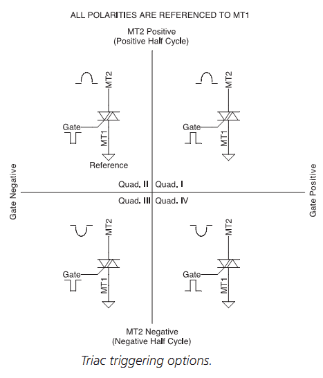
If you take a look here, you can see, the triac is driven differently at different quadrants:
28_1311176007.png


Hope this helps.
Tahmid.
 

I am afraid that A and C are possible and B and D are wrong.
Obviously in A and C, there is a missing resistor in series with the gate to limit its current.

A triac has one input between the terminals G and MT1 (based on your last pics).
A suitable current must pass between G and MT1 for the triac to turn on.

So when the triac is off, there will be a voltage difference MT2 and gate (assuming the opto small triac is on). This voltage will rise sinusoidally till the current passing the gate through MT1 is high enough to trigger it. MT2 and MT1 will have then a small voltage difference.

So even if the opto is on at zero crossing, there will be a delay till MT2 is high enough to trigger the gate.

One may think to lower the value of the resistor so that a lower voltage would be needed for the trigger.
If the optocoupler is of the type with a zero-crossing detector (that is its triac turns on only at zero crossings) then the limiting resistor could have a relatively low value. But for the opto for the random phase trigger, the value of the resistor should be calculated so that at the worst case (that is at 90 deg at which the mains voltage is peak) its current should not exceed the maximum current of the opto triac.

Added:
The maximum current (not continuous) of the opto triac is typically 1 Amp.
 
Last edited:
Obviously in A and C, there is a missing resistor in series with the gate to limit its current.
Yes, the current limiting resistor isn't shown here, but they should be there.

---------- Post added at 21:57 ---------- Previous post was at 21:45 ----------

The diagrams were from the book Programming the PIC Microcontroller with MBasic, chapter: AC Power Control.

However, when I used triac for phase-angle control, I used this configuration:
58_1311177476.png
 
Last edited:

Which one won't work?

on post #26

There is no voltage between the gate and A2.
So even if the opto triac is on there will be no current.

However, when I used triac for phase-angle control, I used this configuration:

Do you have other types of triac there, mine cannot be triggered this way :grin:

================

On the other hand, you are right. If the controller will be placed out of touch there is no need for isolation.
 
Last edited:

No, this, I'm pretty sure, works. I've used this in my inverter. Working for about a year now. From the same book:
82_1311178211.png


---------- Post added at 22:12 ---------- Previous post was at 22:10 ----------

Reference to the inverter (circuits there as well, with PCB): https://www.edaboard.com/threads/195822/
 

That is good (post #30)

When the main triac is off... MT2 voltage will rise hence it can provide a current to the gate-MT1 junction if the opto triac is on.
 

Please, there is a big difference between MT2 and MT1. You can think the gate as if it were the BJT base and MT1 its emitter ... finally MT2 the collector.
 

post #30 and #26 both worked according to some people.. they have already working project using either of the schematics...I dont know much about this but it might be some instance that post 26 will not work... :)
 
Last edited:

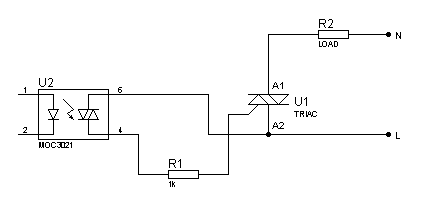
I'm really not sure what you're talking about. The A2 in post #26 is MT2 and A1 is MT1. I see that both the circuits are the same. Please take a look at the circuit in post #26 carefully and carefully look at the Live (Hot) and Neutral connections.
 

And you see they're the exact same thing.

---------- Post added at 22:22 ---------- Previous post was at 22:21 ----------

Just take a look at them. In post #26, the top one is N, the bottom one is L. They're the exact same thing (post 26 and post 30).
 

And you see they're the exact same thing.

---------- Post added at 22:22 ---------- Previous post was at 22:21 ----------

Just take a look at them. In post #26, the top one is N, the bottom one is L. They're the exact same thing (post 26 and post 30).

I see now your confusion... to me, I don't look at the labels but how the gate is placed relative to the other two terminals.


The terminal which is close the the gate one (on the pic) is like the BJT emitter. That is there will be no voltage on them. While the other terminal is isolated from them hence its potential can be different.
 

Compare them, they're the same circuit:

58_1311177476.png
82_1311178211.png


---------- Post added at 22:28 ---------- Previous post was at 22:24 ----------

So you see, they're the same circuit and so, both will work.
 

Status
Not open for further replies.

Similar threads

Part and Inventory Search

Welcome to EDABoard.com

Sponsor

Back
Top