Continue to Site

Welcome to EDAboard.com

Welcome to our site! EDAboard.com is an international Electronics Discussion Forum focused on EDA software, circuits, schematics, books, theory, papers, asic, pld, 8051, DSP, Network, RF, Analog Design, PCB, Service Manuals... and a whole lot more! To participate you need to register. Registration is free. Click here to register now.

need help with alarm circuit [toggle output]

wozzzzza

Member level 4
Member level 4
Joined
Dec 10, 2008
Messages
76
Helped
0
Reputation
0
Reaction score
5
Trophy points
1,288
Visit site
Activity points
1,736
been out of electronics too long and ant work this one out now.
i want to build a circuit, an alarm circuit, that will toggle armed and unarmed with 2 separate high inputs, e.g. one input goes high for half a second to turn it on and another input goes high for half a second that turns it off. no matter how many times a high pulse is sent to the on input, the alarm will remain armed and vica versa.
another n/c input to trigger the alarm out for 5 seconds, so when this input is open circuit it will trigger the alarm output for 5 seconds only when the circuit is armed. after 5 seconds waits for another alarm input.
how can i build something like this easily??

MODERATOR ACTION:
  • Added relevant information on title
 
Last edited by a moderator:
ive gone through the code and recoded it all, see how it goes this time.
Code:
#include <Arduino.h>
#include <Wire.h>
#include <SoftwareSerial.h>

int varArmed = 0;
int varCount = 0;
int varSMS = 0;

void setup() {
  // put your setup code here, to run once:

  pinMode(0,OUTPUT); // pin 5 on IC - alarm output goes to horn relay
  pinMode(1,INPUT); //pin 6 on IC - to door handle switches N/C low input
  pinMode(2,OUTPUT); //pin 7 on IC - GPS trigger SMS notify
  pinMode(3,INPUT); //pin 2 on IC - to door lock High pulse Turn on alarm
  pinMode(4,INPUT); //pin 3 on IC - to door unlock High pulse Turn off alarm

  digitalWrite(0,0); // Alarm off when powered up

}

void loop() {
  // put your main code here, to run repeatedly:

  if(varArmed == 0) {
      //do nothing but wait until armed

      if(digitalRead(3) == 1){   //when doors lock signal goes high temporarily, arm alarm   
        varArmed = 1;
      }
  }//end if

    if(varArmed == 1) { //alarm armed routine

      //digitalWrite(2,1); //armed led on

      if(digitalRead(4) == 1){ //when doors unlock signal goes high temporarily, disarm alarm
        varArmed = 0;
        varSMS = 0;
      }

      //check to see if alarm is triggered
      if(digitalRead(1) == 1){ // N/C switch opens pulling input high
        //Alarm triggered routine
        
        varSMS += 1;
        digitalWrite(0,1);
        if(varSMS < 6){digitalWrite(2,1);}//send SMS notification
        delay(20);
        digitalWrite(0,0);
        digitalWrite(2,0);
        delay(20);
        digitalWrite(0,1);
        delay(20);
        digitalWrite(0,0);
        delay(20);
        digitalWrite(0,1);
        delay(20);
        digitalWrite(0,0);
        delay(20);
      }//end if for alarm routine

    }//end if

}// end void loop
 
Hi,

eventually you divided SETUP part and LOOP part.
Well done. I don´t know how the ARDUINO behaves when the endless loop is in the setup area.
I´ve heard that ARDUINO expects that the loop to be performed within a limited time, or it used some delay() command or a yield() command.

I´m no friend of doing timer stuff in main loop using busy_waits. Thus my solution would use interrupts.

For me a busy_wait is like driving a car in full throttle and using the brake for speed control.

Klaus
 
whats interrupts?

We can´t replace school .
.. there are tutorials, videos, documents, code examples.. just do a search.

It´s a wide area, thus just in short:

Interrupt can - as the name says - interrupt the normal program flow and can do other software parts (ISR) inbetween.

Let´s say you write code (main loop) that is busy doing heavy calculations maybe for 10 seconds (just as an example).
So usually you don´t have the chance to react on key press, UART, ADC ... during this 10 seconds. Which makes the microcontroller look like it was stalled.
Thus you can set up interrupts (many different types).
For example you can set up an interrupt to be raised every 20ms. (And this 20ms are perfectly 20ms, sou you can even design a high precision watch this way)
So every 20ms an additional piece of code is perfomed. It may
* update the software clock counting, to keep it accurate
* look if keys are pressed and released --> and just store the information for later processing
* look if the UART received bytes --> and store the data in a buffer for later processing
These additional code pieces should be short in time, just doing the most essential stuff then returning ... maybe after a couple of microseconds .. to go on processing the usual main code. (in an ISR you avoid delay(), waiting loops and so on)
Let´s say the ISR takes 50 microseconds .. then this means it takes 0.25% of processing power from your main loop.

There are many ways.
Like instead of checking every 20ms whether a key is pressed you may set up a dedicated "pin change interrupt" ... this way you don´t need to reguraily check (poll) the status of the port pins ... it will run the according ISR as soon as the port changes.

Let´s imagine a real life situation:
* you want to read a book ... maybe takes 5 hours (main loop)
* you have your laundry in the machine .. waiting to be finished and put into the dryer (external even interrupt)
* you have a meal on the oven to be stirred every 5 minutes (regular timer interrupt)

With the interrupt method you can focus on reading your book.
But you set up yur washing machine to give an alarm when finished. --> on alarm just move the laundry into the dryer. Then go on reading your book
And you set up your cell phone to beep every five minutes. --> stir the pot, then go back reading your book.

I guess 95% of my programs use interrupts. I like them, they save a lot of processing time and they make an control loop reliably working. Also they help to keep control loop timing constant. In one single project I can run SPI communication, I2C communication, UART communication, 10.000 times per second ADsampling, heater control loop, software clock, data processing, data displaying, data saving, LED blinking, key press, touch control .. all seems to be performed at the same time... with perfect accuracy and without missing a single event.

Klaus
 
Last edited:
Interrupt code design is fairly straight forward but there are simple
methods that insure performance is not compromised by the ISR code
(ISR = Interrupt Service Routine). Like not calling f()'s from within ISR
which causes "stack thrashing". Basically setting a flag and returning
from ISR to process the interrupt. Versus complex coding within ISR.
As Klauss points out.

Also using pointers to variables outside ISR versus copying the when
modified. Or declaring variables as volatile to avoid unwanted variable
modification. Google "c variable volatile embedded"

See attached.


Regards, Dana.
 

Attachments

  • Mastering-Interrupts-A-Guide-for-Embedded-Engineers.pdf
    1.5 MB · Views: 49
Last edited:
what im finding is it will work sometimes and not others. while in armed state it will work one hour, come back to try and trigger it, it wont trigger, come back an hour later it will work again, come back an hour later its not working.
 
could it be an issue with the voltage divider im using for the arm and disarm, possibly disarming and arming at random?
12v pulse from car to turn it on and off.

voltage divider.png
 
Hi,

the answer is in the voltage levels.
I don´t want to go back through 88 posts.

So ask yourself:
* what is the minimum ON voltage at the 12V side
* what is the maximum OFF voltage at the 12 V side.
(Please don´t expect 0.00V and 12.00V to be realistic. A cold, almost discharged battery .. may go way below 12V, stray currents may lift the OFF level up)

After this .. do the math/simulation to see the voltages that reach the microcontroller for ON and OFF
Always tend to go a bit to the worst case side.

Then check the microcontroller datasheet if these are valid pin input levels.

Klaus
 
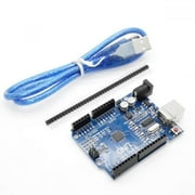
i just hooked up the relay for the horn today and the circuit refuses to work. i have the arduino 5v regulator, the arduino relay board, the relay board controls the horn relay.
as soon as the alarm is triggered the horn beeps once and the alarm circuit resets to disarmed.
got me screwed for a few minutes then i decided to put a diode between the horn relay coil and it worked after that.
was not expecting that at all as relay is not really coupled to the circuit and i expected the 5v arduino supply to be smoothed enough to prevent this sort of stuff.
 
You get a big transient from inductive horn coil, diode suppresses that.

If you have a DSO, w/o diode, do a single shot capture, great way to hose Arduino and or other parts.
 

LaTeX Commands Quick-Menu:

Part and Inventory Search

Welcome to EDABoard.com

Sponsor

Back
Top