Continue to Site

Welcome to EDAboard.com

Welcome to our site! EDAboard.com is an international Electronics Discussion Forum focused on EDA software, circuits, schematics, books, theory, papers, asic, pld, 8051, DSP, Network, RF, Analog Design, PCB, Service Manuals... and a whole lot more! To participate you need to register. Registration is free. Click here to register now.

need help with alarm circuit [toggle output]

wozzzzza

Member level 4
Member level 4
Joined
Dec 10, 2008
Messages
76
Helped
0
Reputation
0
Reaction score
5
Trophy points
1,288
Visit site
Activity points
1,736
been out of electronics too long and ant work this one out now.
i want to build a circuit, an alarm circuit, that will toggle armed and unarmed with 2 separate high inputs, e.g. one input goes high for half a second to turn it on and another input goes high for half a second that turns it off. no matter how many times a high pulse is sent to the on input, the alarm will remain armed and vica versa.
another n/c input to trigger the alarm out for 5 seconds, so when this input is open circuit it will trigger the alarm output for 5 seconds only when the circuit is armed. after 5 seconds waits for another alarm input.
how can i build something like this easily??

MODERATOR ACTION:
  • Added relevant information on title
 
Last edited by a moderator:
No you use the Arduino UNO board selection (or whatever you purchased) -

1732587683257.png
 
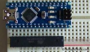
if i get just the ATMEGA328P chip and crystal and few other components, if i use the Arduino Nano as ISP programmer like i do for the attiny85 can i also program the ATMEGA328P on a breadboard with that? with the crystal and capacitor and whatever, will that work?


Google is your friend....
 
having trouble working out what pin does what here, ive got it working with the atmega328P, uploaded the blink code and it said it was done no errors, and i put a led between pin 2, PD0, and earth with 470r resistor and no blink. just on solid.
this is the code, what am i doing wrong?

C:
void setup() {
  // initialize digital pin LED_BUILTIN as an output.
  pinMode(0, OUTPUT);
}

// the loop function runs over and over again forever
void loop() {
  digitalWrite(0, HIGH);  // turn the LED on (HIGH is the voltage level)
  delay(1000);                      // wait for a second
  digitalWrite(0, LOW);   // turn the LED off by making the voltage LOW
  delay(1000);                      // wait for a second
}

1732707060817.png
 
Last edited:
You have

Pin 0 >> LED >> Resistor >> Ground right or Pin 0 >> Resistor >> LED >> Ground right?
The below pin used another pin, pin 9, but you get the idea .....

1732707959245.png


Correct polarity on LED ?

1732708089408.png


Note in your code delay(400) is a delay of 400 mS, not 1 sec.


Regards, Dana.
--- Updated ---

Note pin # versus symbolic pin :

1732709155279.png


1732709185794.png


Use "D5" in code, not "0", given its one of the UART interface pins
 
Last edited:
Last edited:
Then turn Nano into a programmer -


When you wire in breadboard use colored wires, red for +V, Black for ground, pick a color
for digital in, digital out, analog (I use green for that) so that confirming wiring is much easier.
--- Updated ---

Sound Card Oscilloscope :


https://www.electro-tech-online.com...uency-meter-module.165634/page-2#post-1446586 post #38

Make sure you protect sound card inputs and outputs when you do this. No mistakes otherwise you hose your
PC sound capability.

Or use a Nano as a crude oscilloscope : https://projecthub.arduino.cc/Cifer...scilloscope-at-home-using-arduino-nano-3d2a69
On youtube lots of DIY scopes.

If you are new to solderless breadboards -

Note short leads better. Keep in mind they can have contact issues as they are not exactly space age hi quality contact
systems.

If you are new to prototyping one bit of advice. Its easy to accidentally apply a high V
to a valuable part pin, and blow it up. Use a series R to each pin, say 1K, generally that will
limit current so pin / part is not damaged. When you are confident you can remove the
R's. Note generally dont do that to power pins as part may not operate properly. When you
do this to inputs generally no problem, output's it can reduce drive levels so keep that in
mind.
 
Last edited:
well none of that is working, just error after error. maybe too old.
If I´m not mistaken you DID NOT report any error message at least for the last 50 posts.
(Capital letters are not meant as a shout, but for emphasis)

If you don´t give the informations .. you need to rely on some people having a crystal ball .. to be able to help you.

Klaus
 
If I´m not mistaken you DID NOT report any error message at least for the last 50 posts.
(Capital letters are not meant as a shout, but for emphasis)

If you don´t give the informations .. you need to rely on some people having a crystal ball .. to be able to help you.

Klaus
fair enough. following those instructions i think to the letter of https://www.martyncurrey.com/arduino-nano-as-an-isp-programmer/
get error of "Property 'bootloader.tool.serial' is undefined" when it gets to burning boot loader
 

LaTeX Commands Quick-Menu:

Part and Inventory Search

Welcome to EDABoard.com

Sponsor

Back
Top