Continue to Site

Welcome to EDAboard.com

Welcome to our site! EDAboard.com is an international Electronics Discussion Forum focused on EDA software, circuits, schematics, books, theory, papers, asic, pld, 8051, DSP, Network, RF, Analog Design, PCB, Service Manuals... and a whole lot more! To participate you need to register. Registration is free. Click here to register now.

need help with alarm circuit [toggle output]

wozzzzza

Member level 4
Member level 4
Joined
Dec 10, 2008
Messages
76
Helped
0
Reputation
0
Reaction score
5
Trophy points
1,288
Visit site
Activity points
1,736
been out of electronics too long and ant work this one out now.
i want to build a circuit, an alarm circuit, that will toggle armed and unarmed with 2 separate high inputs, e.g. one input goes high for half a second to turn it on and another input goes high for half a second that turns it off. no matter how many times a high pulse is sent to the on input, the alarm will remain armed and vica versa.
another n/c input to trigger the alarm out for 5 seconds, so when this input is open circuit it will trigger the alarm output for 5 seconds only when the circuit is armed. after 5 seconds waits for another alarm input.
how can i build something like this easily??

MODERATOR ACTION:
  • Added relevant information on title
 
Last edited by a moderator:
So here is a working version :

1728937492191.png


Note settings :

1728937607506.png


Set clk to 1 Mhz, and your programmer to the one you are using.

So when alarm pushed > .5 sec alarm comes on and stays on for min 5 sec. Only when off
pushed > .5 sec is it turned off, and stays off min 5 sec, then can be triggered on again. Is that
what you wanted ?

Note board selection -

1728937943225.png


Regards, Dana.
--- Updated ---

Trigger -

1728939836534.png


Note the min pulse is 5.5 sec due to off button delay of .5 sec, so values used for delays could
be fiddled with. But you can see alarm triggered after .5 sec and width is .5 + 5 sec.

Regards, Dana.
 

Attachments

  • Two Button Alarm.zip
    54.8 KB · Views: 38
Last edited:
So here is a working version :


Note settings :


Set clk to 1 Mhz, and your programmer to the one you are using.

So when alarm pushed > .5 sec alarm comes on and stays on for min 5 sec. Only when off
pushed > .5 sec is it turned off, and stays off min 5 sec, then can be triggered on again. Is that
what you wanted ?

Note board selection -


Regards, Dana.
--- Updated ---

Trigger -


Note the min pulse is 5.5 sec due to off button delay of .5 sec, so values used for delays could
be fiddled with. But you can see alarm triggered after .5 sec and width is .5 + 5 sec.

Regards, Dana.
not sure yours was quite right for my application, i have 2 inputs, one input goes high temporarily to arm alarm, other input goes high temporarily to disarm alarm.
just spent the last hour coding this one up, what you think of this? it compiles ok. just haven't had time to test it out yet.
just not sure if the variable 'varArmed' used is read within all the functions or need to be changed, been 15+ years since i did coding last.
 

Attachments

  • alarm.zip
    858 bytes · Views: 37
not sure yours was quite right for my application, i have 2 inputs, one input goes high temporarily to arm alarm, other input goes high temporarily to disarm alarm.
just spent the last hour coding this one up, what you think of this? it compiles ok. just haven't had time to test it out yet.
just not sure if the variable 'varArmed' used is read within all the functions or need to be changed, been 15+ years since i did coding last.

You declared the variable as public so you are all set. All functions have R/W access to it.

Note you have a mix of code struc from my mBlock code and "normal" Arduino code -

Code:
void setup() {
  // put your setup code here, to run once:

}

void loop() {
  // put your main code here, to run repeatedly:

}

Normally you put one time code in setup(), like pin setup, serial setup...etc., and the runtime main code in loop()

Just a thought, consistent with "normal" pra ctice.
 
Last edited:
Better Alarm circuits use a Resistor so that an open or short becomes a fault rather than a true remote alarm. It is called end of line resistor EOLR.

If you want a simpler solution, define your alarm circuit for both states in terms of voltage or if you prefer using the 0V side open/closed. Then there are many simple DUAL SWITCHES for ARM/DISARM. Describe how far apart these switches are from the alarm.
 
You declared the variable as public so you are all set. All functions have R/W access to it.

Note you have a mix of code struc from my mBlock code and "normal" Arduino code -

Code:
void setup() {
  // put your setup code here, to run once:

}

void loop() {
  // put your main code here, to run repeatedly:

}

Normally you put one time code in setup(), like pin setup, serial setup...etc., and the runtime main code in loop()

Just a thought, consistent with "normal" pra ctice.

You declared the variable as public so you are all set. All functions have R/W access to it.

Note you have a mix of code struc from my mBlock code and "normal" Arduino code -

Code:
void setup() {
  // put your setup code here, to run once:

}

void loop() {
  // put your main code here, to run repeatedly:

}

Normally you put one time code in setup(), like pin setup, serial setup...etc., and the runtime main code in loop()

Just a thought, consistent with "normal" practice.

Now I see your desired functionality, one button arms the alarm, and if door open an alarm occurs
for a minimum of 5 secs, and stays in alarm state until door closed OR arm off button pushed ?

OR

One button arms the alarm, and if door open an alarm occurs for 5 secs, and then turns off ?
 
Now I see your desired functionality, one button arms the alarm, and if door open an alarm occurs
for a minimum of 5 secs, and stays in alarm state until door closed OR arm off button pushed ?

OR

One button arms the alarm, and if door open an alarm occurs for 5 secs, and then turns off ?
it is actually connected to door handles, so if someone tries to open the door when car locked it sets horn off to scare them off.
its a big issue where i live youth crime, they go around the streets at night into peoples yards trying to find unlocked cars and houses to break into. this is used to scare them off if they try mine. i have rigged a N/C reed switch up to the door handles inside the door.
So where is the reset switch? remote control? and is the output a 10A horn? or a 0.05A relay coil or ??
 
how do you debug these scripts?? not working as intended.
power it up all ok, arm alarm that works ok. remove the high for a second to trigger it, sets alarm sounding, but wont turn off for about 1 minute afterwards. delay is 5 seconds.
i have 22k resistor as pull down on trigger, but that shouldn't make any difference as it is high all the time unless triggered.
any ideas?
--- Updated ---

So where is the reset switch? remote control? and is the output a 10A horn? or a 0.05A relay coil or ??
armed and disarmed from the cars central locking high pulse for lock and unlock. output goes directly to 10A horn from IC, na only joking, i have an ardruino relay board that will trigger another relay that will set horn going.
--- Updated ---

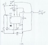
heres the circuit
 

Attachments

  • circuit.jpg
    circuit.jpg
    119.5 KB · Views: 35
Last edited:
Does that mean the Output is an Arduino 5V 90 mA coil 10A relay? or what?

What are the reed switches wired to? +12, +5 or gnd? How many? ganged together? twisted pair wires or what? series R or pullup or down?

Normally all remote alarm switches are grounded with remote pullups.

This is pretty trivial without an Arduino.
this is the exact relay board

reed switches are wired in series like in circuit connected to +5v and trigger pin on chip

can do either way i guess high or low trigger, just a matter of changing a 1 to a 0

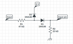
the high arm and disarm will be through a voltage divider as that is 12V triggers
 

Attachments

  • voltage divider.png
    voltage divider.png
    11.8 KB · Views: 36
Hi,
its a big issue where i live youth crime, they go around the streets at night into peoples yards trying to find unlocked cars and houses to break into.
Then my car would be the first to be found unlocked. I can not remember when I locked it last time.

I´m sure there are cheap ready to buy car alarm that do exactly what you want.
I guess you spend more time and money by building it on your own.

Klaus
 
Hi,


I´m sure there are cheap ready to buy car alarm that do exactly what you want.
I guess you spend more time and money by building it on your own.

Klaus
can you find one? i doubt it, never seen one around for this application that connects to the car itself without separate remote, i have to install reed switches on handle mechanism itself to make it work, only other car i can think of is a tesla that may do similar.
i like doing stuff myself as well.
 
Hi,

recently a friend brought me defective one for check/repair. It was a cheap chinese one without schematic.
It was rather simple to connect without extra switches. I guess the installation was only under the dashboard. Don´t know if it had an RC.

I´m not familiar with what different types are around ... I guess it differs from country to country ... and for what car brand/type to use.
I did not do a research so far.

*****
And for sure you are free to do design your own circuits ...

Klaus
 
whats the flow of this program sequence?
when powered up it it runs from the top down, gets variables setup that are declared, runs the setup() function and where does it go from there? just continues the loop() function endlessly no matter what you do?? once whatever function you want it to perform, once it completes that it will go back to the beginning of the loop function?
 
In the neighborhood where I live I hear some car every other day honking its horn repeatedly, lasting for 10 or 20 seconds. Sometimes I think it's the wind rocking a car.

Getting familiar with my own car I discovered two means of locking it. (It's a 2006 model for which I lack a fob.) There's a switch inside near the electric window switches. This locks and unlocks all doors. In addition it arms the anti-theft system in an unexpected manner. Because later when I unlocked the driver's door with my key and opened the handle, my horn immediately honks loud enough to wake the dead. I have to close it to silence it, then open it again.

It was annoying until I tried a different method. I exit the car and lock it with my key. From seeing a flashing led inside, the anti-theft system is armed. Yet it stays silent when I use my key next time.

This may or may not be how other cars behave. Is it an option for OP in his car?
 
20 years ago when I lived in Winterpeg, all the old cars without modern (faulty) secure door alarms could get a free "Interruptor" alarm installed under the hood where it cannot be bypassed. It was free from the best Gov't-owned public car insurance company called Autopac. (best in service and rates)

I wonder why the car industry is so lax in security. A simple wireless, rolling-code ignition "interrupter" circuit hidden under the locked hood will take a lot more than 60 seconds to bypass with a damaged hood lock to steal.


Only people with nice new cars have to worry in Toronto so my 6 yr old Merc SUV never gets locked unless my wife insists. Same with our 30 yr old house.
In Winnipeg on the outskirts, farmers even leave the keys in their trucks with a long driveway. Autopac might not like you for that if it gets stolen and give less than the advertised equivalent value.

My wife's old Mazda 6 used to randomly trigger the alarm at any time and then timeout after a minute. I figured out it was the door switch getting oxidized (N.C.) so I sprayed WD-40 on the passenger side alarm switch and it hasn't happened for a while. (if they aren't gold-plated air switches, they will oxidize! but I don't know if the auto industry has the same standards as the Telecom switch industry. I figured out this trick 50 yrs ago in the aerospace industry to add 10uF cap on a logic sense contact for P&B Relays to "wet" the contacts)
 
Last edited:
got it working, works as i want but one big problem i cant work out why. once i lock the doors on car it will work fine for a few hours but when i come back a few hours later it is no longer working until i unlock and lock the car again. then few hours later it stops working again.
any ideas??
C++:
#include <Arduino.h>
#include <Wire.h>
#include <SoftwareSerial.h>

int varArmed = 0;
int varCount = 0;
int varSMS = 0;

void _delay(float seconds) {
  long endTime = millis() + seconds * 80;
  while(millis() < endTime) _alarm();
}

void setup() {
  pinMode(0,OUTPUT); // pin 5 on IC - alarm output goes to horn relay
  pinMode(1,INPUT); //pin 6 on IC - to door handle switches N/C low input
  pinMode(2,OUTPUT); //pin 7 on IC - GPS trigger SMS notify
  pinMode(3,INPUT); //pin 2 on IC - to door lock High pulse Turn on alarm
  pinMode(4,INPUT); //pin 3 on IC - to door unlock High pulse Turn off alarm

  digitalWrite(0,0); // Alarm off when powered up

  while(varArmed == 0) {
      //do nothing but wait until arm and make sure it does not sound alarm

      digitalWrite(0,0); //ensure alarm output is off
      //digitalWrite(2,0); //armed led off

      if(digitalRead(3) == 1){   //when doors lock signal goes high temporarily, arm alarm   
        varArmed = 1;
      }
      _loop();
  }

    while(varArmed == 1) { //alarm armed routine

      //digitalWrite(2,1); //armed led on

      if(digitalRead(4) == 1){ //when doors unlock signal goes high temporarily, disarm alarm
        varArmed = 0;
        varSMS = 0;
        break;
      }

      //check to see if alarm is triggered
      if(digitalRead(1) == 1){ // N/C switch opens pulling input high
        //Alarm triggered routine
        
        varSMS += 1;
        digitalWrite(0,1);
        if(varSMS < 6){digitalWrite(2,1);}//send SMS notification
        delay(20);
        digitalWrite(0,0);// turn alarm off when 3 seconds up ready to go again
        digitalWrite(2,0);
        delay(20);
        digitalWrite(0,1);
        delay(20);
        digitalWrite(0,0);// turn alarm off when 3 seconds up ready to go again
        delay(20);
        digitalWrite(0,1);
        delay(20);
        digitalWrite(0,0);// turn alarm off when 3 seconds up ready to go again
        delay(20);
      }

      _loop();
    }

    setup();

}
void _alarm() { // once alarm triggers, if disarmed it turns off alarm

      varCount += 1;
      if(digitalRead(4) == 1){ //when doors unlock signal goes high temporarily, disarm alarm instantly
        varArmed = 0;
        varCount = 0;
        digitalWrite(0,0); //turn alarm off
        setup();
      }else{
         //pulse the horn in a sequence so i know its mine
        //if(varCount < 15) {
            //digitalWrite(0,1);
        //  }else if(varCount < 20){
        //    digitalWrite(0,0);
         // }else if(varCount < 25){
         //   digitalWrite(0,1);
         // }else if(varCount < 30){
        //    digitalWrite(0,0);
        //  }else{
         //   varCount = 0;
         //   digitalWrite(0,0);
        //}
      }

}

void alarm() {
  _alarm();
}

void _loop() {
}

void loop() {
  _loop();
}
 
To build the alarm circuit you described, you'll need to design a system with two primary states: armed and unarmed. The alarm is toggled between these two states by separate high pulses, and the alarm triggers only when the system is in the armed state. Additionally, the alarm should be triggered for a fixed duration (5 seconds) by a normally closed (N/C) input, and then reset to wait for the next alarm input.
been out of electronics too long and ant work this one out now.
i want to build a circuit, an alarm circuit, that will toggle armed and unarmed with 2 separate high inputs, e.g. one input goes high for half a second to turn it on and another input goes high for half a second that turns it off. no matter how many times a high pulse is sent to the on input, the alarm will remain armed and vica versa.
another n/c input to trigger the alarm out for 5 seconds, so when this input is open circuit it will trigger the alarm output for 5 seconds only when the circuit is armed. after 5 seconds waits for another alarm input.
how can i build something like this easily??
 

LaTeX Commands Quick-Menu:

Part and Inventory Search

Welcome to EDABoard.com

Sponsor

Back
Top