Continue to Site

Welcome to EDAboard.com

Welcome to our site! EDAboard.com is an international Electronics Discussion Forum focused on EDA software, circuits, schematics, books, theory, papers, asic, pld, 8051, DSP, Network, RF, Analog Design, PCB, Service Manuals... and a whole lot more! To participate you need to register. Registration is free. Click here to register now.

need help with alarm circuit [toggle output]

wozzzzza

Member level 3
Member level 3
Joined
Dec 10, 2008
Messages
64
Helped
0
Reputation
0
Reaction score
5
Trophy points
1,288
Activity points
1,681
been out of electronics too long and ant work this one out now.
i want to build a circuit, an alarm circuit, that will toggle armed and unarmed with 2 separate high inputs, e.g. one input goes high for half a second to turn it on and another input goes high for half a second that turns it off. no matter how many times a high pulse is sent to the on input, the alarm will remain armed and vica versa.
another n/c input to trigger the alarm out for 5 seconds, so when this input is open circuit it will trigger the alarm output for 5 seconds only when the circuit is armed. after 5 seconds waits for another alarm input.
how can i build something like this easily??

MODERATOR ACTION:
  • Added relevant information on title
 
Last edited by a moderator:
i did a small program in mblock and this is the code it spits out
C++:
// generated by mBlock5 for <your product>
// codes make you happy

#include <Arduino.h>
#include <Wire.h>
#include <SoftwareSerial.h>

void _delay(float seconds) {
  long endTime = millis() + seconds * 1000;
  while(millis() < endTime) _loop();
}

void setup() {
  pinMode(3,OUTPUT);
  while(1) {
      digitalWrite(3,1);
      _delay(float(random(1, 5 +1)));
      digitalWrite(3,0);
      _delay(float(random(1, 5 +1)));

      _loop();
  }

}

void _loop() {
}

void loop() {
  _loop();
}

when copied and pasted into IDE and compiled it spits the dummy with thousands of errors.
now if i delete the 3 includes at the top and compile it again it compiles fine and uploads and works perfectly.
so why does mblock include these includes??
 
Those are relatively standard includes, did you do the steps in post #40, reinstall Arduino IDE ? The newest version ?

By the way, when you do have the includes whats the very first error, copy and paste, you get ?
 
Last edited:
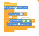
This will sound alarm for min 5 sec, after than stay off until alarm off button pushed.

View attachment 194372


Regards, Dana
how do you get the read digital pin = 5? i can only get it to do below
--- Updated ---

Those are relatively standard includes, did you do the steps in post #40, reinstall Arduino IDE ? The newest version ?

By the way, when you do have the includes whats the very first error, copy and paste, you get ?
im on the latest IDE 2.3.3

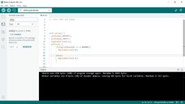
first code it gives is
C:\Users\Wozzzzza\AppData\Local\Arduino15\packages\arduino\hardware\avr\1.8.6\libraries\Wire\src\utility\twi.c: In function 'twi_init':
 

Attachments

  • mblock2.jpg
    mblock2.jpg
    51.6 KB · Views: 26
Then I am lost on why the intrinsic libs not found, post this problem in Arduino forum,
they should be able to fix this. Curious, when you did the upgrade did you erase the folders I suggested
in post #40 ?

When you post there post project code, and the entire output from compile.

The project I posted shows the following code :

Code:
// generated by mBlock5 for <your product>
// codes make you happy

#include <Arduino.h>
#include <Wire.h>
#include <SoftwareSerial.h>

void _delay(float seconds) {
  long endTime = millis() + seconds * 1000;
  while(millis() < endTime) _loop();
}

void setup() {
  pinMode(9,OUTPUT);
  pinMode(5,INPUT);
  pinMode(6,INPUT);
  // Alarm drive pin off when powered up
  digitalWrite(9,0);
  while(1) {
      // Alarm input on pin high
      if(digitalRead(5) == 1.000000){
        _delay(0.5);
        // Alarm input still on after .5 secs ? Then
        // turn on alarm
        if(digitalRead(5) == 1.000000){
          digitalWrite(9,1);
          // Alarm on for min of 5 sec
          _delay(5);

        }

      }
      // Alarm off pin high ?
      if(digitalRead(6) == 1.000000){
        _delay(0.5);
        // Alarm off input still on after .5 secs ? If so turn it off
        if(digitalRead(6) == 1.000000){
          digitalWrite(9,0);

        }

      }

      _loop();
  }

}

void _loop() {
}

void loop() {
  _loop();
}

1728736844324.png
 
the pin declarations you have here
pinMode(9,OUTPUT);
pinMode(5,INPUT);
pinMode(6,INPUT);
this is not for the attiny85 is it? as only has 6 I/O??
 
1728737116068.png


I was doing the project on the Nano, you will have to pick a different pin for button input on ATTINY85.
PB0, 1, 2 Also change output pin.

Regards, Dana.
 
im just giving up and deleting the includes.
but im wondering why there is a 2 second delay in this script i wrote?
starts up led is on, when you send pin 4 high it turns led off instantly, but take the high off pin 4 it takes 2 seconds before the led turns back on again, im expecting instantly. any reason 2 second delay?

C-like:
void setup() {
  pinMode(3,OUTPUT);
  pinMode(4,INPUT);
  digitalWrite(3,1);
  while(1) {
      if(digitalRead(4) == 1.000000){
        digitalWrite(3,0);

      }else{
        digitalWrite(3,1);
      }

      
  }

}
 
Hi,
there is a 2 second delay in this script i
I don´t see a dely at all ... What do you mean?

thus I guess this is not a software problem at all, but a hardware problem..

when you send pin 4 high it turns led off
so far so good

but take the high off pin 4 it takes 2 seconds before the led turns back on again
Simple question: Did you set pin 4 to LOW??

--> My guess: you did not, you just left pin 4 floating.
Floating menas undefined. It my be HIGH, it may be LOW, it may be inbetween, it may change, fast or slow. Indeed you don´t know.

If you want it to be LOW, you have to MAKE it LOW.
* Either the same way as you set it HIGH ...
* or by defualt by using a pull down resistor (maybe 10k is a good start)
* or by programming a pull down if your microcontroller allows it.

Klaus

P.S.:
please next time .. when you report a problem: Give us the full information:
* Software (given)
* microcontroller type, clock type and frequency, fuse setting (there is a chance that this "delay" is caused by a watchdog function)
* schematic
* test setup. A rather detailed description what you did
* your expectation
* tell us what exactly was not like expected
Sketches and photos (10kByte max) will help a lot.
 
Last edited:
Hi,

I don´t see a dely at all ... What do you mean?

thus I guess this is not a software problem at all, but a hardware problem..


so far so good


Simple question: Did you set pin 4 to LOW??

--> My guess: you did not, you just left pin 4 floating.
Floating menas undefined. It my be HIGH, it may be LOW, it may be inbetween, it may change, fast or slow. Indeed you don´t know.

If you want it to be LOW, you have to MAKE it LOW.
* Either the same way as you set it HIGH ...
* or by defualt by using a pull down resistor (maybe 10k is a good start)
yes your right i didnt, but i just tried that then, 10k resistor to ground, it turned the led off when i put the resistor in without it even going high. wtf??
 
Arduino pins on startup (and pullup effects) :


I think one of the key issues I missed on install in prior posts one has to install the ATTINY core into IDE :


When you did the 2.3.3 install did you erase the prior installation left over folders ? Eg. post # 40 ?
 
Last edited:
Arduino pins on startup (and pullup effects) :


I think one of the key issues I missed on install in prior posts one has to install the ATTINY core into IDE :


When you did the 2.3.3 install did you erase the prior installation left over folders ? Eg. post # 40 ?
yes i erased everything manually after uninstalling.
ive got some sort of attiny installed
 

Attachments

  • attiny.jpg
    attiny.jpg
    122.2 KB · Views: 26
im just giving up and deleting the includes.

Just some advice, this will plague you for some time to come, severely limit your
future ability to do stuff. Posting at Arduino Forum will help straighten out the issue.
The Wire and Arduino libs are intrinsic to using Arduino, inability to use them will
be like driving a car without an engine.

Just a thought......
--- Updated ---

I think I found possible issue with your includes, that Mellis board lib is almost 10 years old,
last rev. Arduino has probably done 10 revs of their libs since then.

I was able to compile with includes lib I used.

Some board libs for ATTINY recommendations :


I used this one - https://github.com/SpenceKonde/ATTinyCore it has had revisions as recently as 3 months ago

Install :

Boards Manager Installation​

This core can be installed using the boards manager. The boards manager URL is:


  1. File->Preferences on a PC, or Arduino->Preferences on a Mac, enter the above URL in "Additional Boards Manager URLs
  2. Tools -> Boards -> Boards Manager...
  3. Select "ATTinyCore by Spence Konde" and click "Install".

Then exit and re-enter Arduino, and pick the Konde board lib, install it, and then
pick a choice from this as board.

1728830488189.png


I was able to compile the mBlock project with includes fine.

Last uninstall the mellis lib using boards manager just to insure nothing in it conflicts
with the above ATTINY preferred lib.


Regards, Dana.
 
Last edited:
Just some advice, this will plague you for some time to come, severely limit your
future ability to do stuff. Posting at Arduino Forum will help straighten out the issue.
The Wire and Arduino libs are intrinsic to using Arduino, inability to use them will
be like driving a car without an engine.

Just a thought......
--- Updated ---

I think I found possible issue with your includes, that Mellis board lib is almost 10 years old,
last rev. Arduino has probably done 10 revs of their libs since then.

I was able to compile with includes lib I used.

Some board libs for ATTINY recommendations :


I used this one - https://github.com/SpenceKonde/ATTinyCore it has had revisions as recently as 3 months ago

Install :


Then exit and re-enter Arduino, and pick the Konde board lib, install it, and then
pick a choice from this as board.

View attachment 194577

I was able to compile the mBlock project with includes fine.

Last uninstall the mellis lib using boards manager just to insure nothing in it conflicts
with the above ATTINY preferred lib.


Regards, Dana.
now that works all ok, everything compiles with the includes.
now i just need to get rid of that 2 second delay in the led turning back on after removing the high from pin 4, this is annoying me, when i put the 10k resistor on pin4 to earth it led just stays off for some reason
 
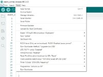
Show your settings and your board selection as well. So I can see the whole picture.

Code:
#include <Arduino.h>
#include <Wire.h>
#include <SoftwareSerial.h>

void setup() {
  pinMode(3,OUTPUT);
  pinMode(4,INPUT);
  digitalWrite(3,1);
  while(1) {
      if(digitalRead(4) == 1.000000){
        digitalWrite(3,0);

      }else{
        digitalWrite(3,1);
      }
  }
}

So timeline I see

1) pin 3 goes to logic 0, output.
2) pin 4 set to input, so its floating unless you have a p/u or p/d
on it
3) if pin 4 is floating (you dont have a p/u or p/d) and you do a read, over time its leakage will slowly
change its state, So there will be a long delay after you release your button.

That may explain your issue.

1728864756268.png


The above, pick one, is what your interface should look like for the button.

And you should code to bounce in and out the button before you act on it.

You can bounce in and act, but preferred is in and release unless you want the
earlier behavior, bounce in-act-bounce out.
 
Last edited:
these setting attached?
the resistor i have set up is on the right hand side in your diagram.
 

Attachments

  • settingsn.jpg
    settingsn.jpg
    78.2 KB · Views: 29
You sure the R is grounded ? Your button is released ?

What value R is it ?

What do LED connections look like ?
 
You sure the R is grounded ? Your button is released ?

What value R is it ?

What do LED connections look like ?
yes im an idiot. i had resistor connected to pin 1 of the chip not ground. now i have it connected the right way it works as expected
thanks.
 
i had resistor connected to pin 1 of the chip not ground. now i have it connected the right way it works as expected
thanks.
this is why I wrote the "P.S." in post#48

... not following this .. wasted 15 hours of your time...

Klaus
 

LaTeX Commands Quick-Menu:

Part and Inventory Search

Welcome to EDABoard.com

Sponsor

Back
Top