Continue to Site

Welcome to EDAboard.com

Welcome to our site! EDAboard.com is an international Electronics Discussion Forum focused on EDA software, circuits, schematics, books, theory, papers, asic, pld, 8051, DSP, Network, RF, Analog Design, PCB, Service Manuals... and a whole lot more! To participate you need to register. Registration is free. Click here to register now.

Audio Amplifier. Which class should I use?

Status
Not open for further replies.
Thanks a lot godfreyl. I was hoping that you would reply to me.

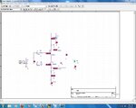
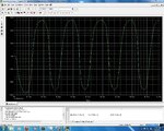
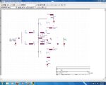
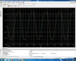
Here is my attachment as you said. I changed frequency to 5000KHz from 20KHz

godfreyl if you see I need help and goldsmith is offline or you can see if I must know this thing then you please help me. I am very great full to you for this.

- - - Updated - - -

@godfreyl can you tell me why law about biasing BE of class AB is important. Can you give me explanation about this? post#144
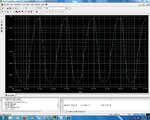
 

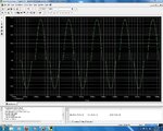
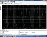
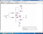
Attachments

  • CE test results.JPG
    CE test results.JPG
    313.3 KB · Views: 85
  • CE test.JPG
    CE test.JPG
    178.6 KB · Views: 79

Hi shayaan
Congratulations ! increase the step to see a better waveform . and remember that your circuit need bias for base-emitter junction too .

And about BE biasing : as you probably can see in the out put shape , it has crossover distortion . it is due to the BE junction . those diodes are not on . and your signal should be able to turn them one . hence if you don't bias them with enough DC voltage , your out put will have crossover distortion . you understand ?
Best Wishes
Goldsmith
 

And about BE biasing : as you probably can see in the out put shape , it has crossover distortion . it is due to the BE junction . those diodes are not on . and your signal should be able to turn them one . hence if you don't bias them with enough DC voltage , your out put will have crossover distortion . you understand ?

Nice explanation. Thanks sir.

So Now I should connect bases of the two transistors with diodes. Right?
 

With diodes and resistors ! can you remember the solution for CC complementary amp ? ( trough two resistor and two diodes ?)
 

I think I should use diodes across BE junction of each capacitor or may be use diodes to connect bases of the two transistors.
 

I think I should use diodes across BE junction of each capacitor
What ?????
BTW : you'd better to use a resistor in series with the common mode ( emitters ) to the ground to provide a little negative feedback to reduce THD.
You should create a DC path for diodes .
A guidance : in parallel with BE junction . BTW : don't forget to add that feedback resistor .
 

It seems good , but why you forgot to increase the step of simulation ? do you know how to increase the step ? if no i can explain it .
And the other thing : why you forgot to add feed back resistor in emitter ?
 

1) No I don't know how to increase step of simulation. What will be its benefit?

2) And does adding feedback resistors decrease THD? How?

3) And I have added collector to base resistors. Did I do right this?

- - - Updated - - -

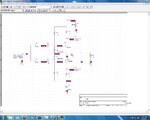
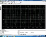
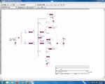
Here is attachment. I have added feedback resistors. But I don't see anything different. The waveform before adding these feedback resistors and after them is almost same. What difference should I notice there?

- - - Updated - - -

Here is attachment. I have added feedback resistors. But I don't see anything different. The waveform before adding these feedback resistors and after them is almost same. What difference should I notice there?
 

Attachments

  • CE test result.JPG
    CE test result.JPG
    312.3 KB · Views: 78
  • CE test.JPG
    CE test.JPG
    182.2 KB · Views: 81

3) And I have added collector to base resistors. Did I do right this?
of course it is correct . you made me hopeful ! my friend .
2) And does adding feedback resistors decrease THD? How?
There is a node that emitters connected together and then this node connected to the ground . you should use a low value resistor between that node and ground . ( such as 10 ohms ) this action will reduce the gain but it will increase BW and decrease THD as well .
1) No I don't know how to increase step of simulation. What will be its benefit?
It will help you to see higher quality , results .
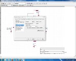
See below ,please :
Spice.JPG
What is the value of maximum step size in your simulations ? ;-)

- - - Updated - - -

Here is attachment. I have added feedback resistors. But I don't see anything different. The waveform before adding these feedback resistors and after them is almost same. What difference should I notice there?
Is that feed back resistor ????? see what i told .
 

Here is my both attachments i.e. resistor at node of emitter to ground and simulation profile. How to change steps?
 

Attachments

  • CE test result.JPG
    CE test result.JPG
    311.8 KB · Views: 73
  • CE test.JPG
    CE test.JPG
    181.6 KB · Views: 77
  • Simulation profile.JPG
    Simulation profile.JPG
    183.3 KB · Views: 76

Shayaan , are you designing an audio amplifier ? if yes i don't think that there is any human available that can hear 5000KHZ ( 5MHZ ) ! change it to 20KHZ if you don't want make a transmitter ! .
And change your alignments to these :
 

OK thanks goldsmith. I have changed frequency.

But I am still getting cross over distortion. And at 5V amplitude I was getting clipping. So I changed amplitude to 3V. I am attaching both with 5V and 3V results so that you could see difference and could know why I changed 5V to 3V.

But what about cross over distortion?

- - - Updated - - -

Also I have increased steps according to your suggestion and provided image.
 

Attachments

  • at 3V.JPG
    at 3V.JPG
    354.8 KB · Views: 75
  • at 5V.JPG
    at 5V.JPG
    316 KB · Views: 73
  • CE test.JPG
    CE test.JPG
    181.8 KB · Views: 72

Use 1n4148 instead of those diodes and use these transistors : BD135 and BD136

- - - Updated - - -

Use 1n4148 instead of those diodes and use these transistors : BD135 and BD136
 

Sir I don't have 1n4148 diodes instead I have D1n4148 in library diodes.
And don't have BD135 and BD136 in library bipolar.

Do you have these components in libraries?
 

did you added all of the libraries ? if yes , type this : D1n4148 and BD136 or BD135 . i think i told you how to add all of the libraries ? didn't i ?
 

Yes you told me and I have added all libraries. And I searched parts. But they are not found. Is there not any alternative?

And kindly tell me which version are you using of pspice?

- - - Updated - - -

Yes you told me and I have added all libraries. And I searched parts. But they are not found. Is there not any alternative?

And kindly tell me which version are you using of pspice?
 

Status
Not open for further replies.

Similar threads

Part and Inventory Search

Welcome to EDABoard.com

Sponsor

Back
Top