Continue to Site

Welcome to EDAboard.com

Welcome to our site! EDAboard.com is an international Electronics Discussion Forum focused on EDA software, circuits, schematics, books, theory, papers, asic, pld, 8051, DSP, Network, RF, Analog Design, PCB, Service Manuals... and a whole lot more! To participate you need to register. Registration is free. Click here to register now.

Audio Amplifier. Which class should I use?

Status
Not open for further replies.
BTW : at class A amplifier , we have a capacitor in out put too . but it will work fine ! why that capacitor isn't important ?
In a class A amplifier, the current through the coupling capacitor is an AC waveform. There is no DC current through the capacitor.

In this circuit, the current through the capacitor is a rectified waveform, so there is DC current as well as AC.
 

Are you joking godfreyl ? what you're trying to say ?? capacitor will block the DC . and will be short circuit for AC . it is exactly the action that you'll see in sepic converters . blocking DC and conducting AC . the AC signal through capacitor has DC component but it isn't any problem .
 

Be patience ! i don't want confuse shayaan . i want he be able to see some problems in practice . as i told , i didn't refer to this circuit . it is completely difference with thing that is in my mind . but we can optimize it . so you can tolerate .
This is what I thought: First you show him a bad circuit, so he can see the problems. Then you guide him to make a better circuit. I just wanted to help him see the problem in the bad circuit.
 

BTW ; see this diagram : what is the summation between those waveforms ? :
Currents.JPG
Of course the result will be a sinusoidal component .
This is what I thought: First you show him a bad circuit, so he can see the problems. Then you guide him to make a better circuit. I just wanted to help him see the problem in the bad circuit.
Yes it is the best way to educate the other ones . i learned this way from an old man , many years ago .
Best Regards
Goldsmith
 

Are you joking godfreyl ?
No, I am not joking.

what you're trying to say ?? capacitor will block the DC . and will be short circuit for AC .
The capacitor should pass AC voltage and block DC voltage. In this circuit, you want the DC voltage across the capacitor to stay constant, but it will not.

You still have not tested the circuit properly, so I will show you pictures.


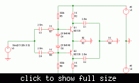
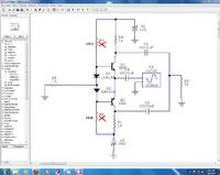
This is the circuit I used:


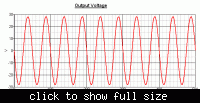
This is the output voltage:


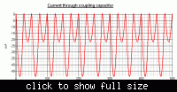
This is the current flowing through one output capacitor:

Can you see that there is DC current flowing through the capacitor? That means it is slowly discharging, so the "DC" voltage across the capacitors is slowly changing. This also means the "DC" voltage across the transistors is slowly changing. The circuit will not work well for long.


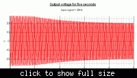
This is what the output voltage looks like if you test for five seconds:

Can you see that the output voltage is limited to half the supply voltage after a few seconds? If you want +-30V output for more than a few seconds, you will need at least a +-60V power supply.


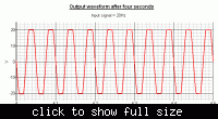
This is the output waveform after four seconds:

Can you see that it is different to the waveform at the start?


Sorry for the delay. It took some time for me to do your testing for you.

- - - Updated - - -

Here is my CB complementary.
Only 5V output? I think the transistors are saturated. If you look at the voltage on the collector of each transistor, you will see the problem.

When you test a circuit, it is important to check the DC operating points before you apply an input signal. This means to check that the DC voltage at each point in the circuit is correct.

In this case, the bias is too much.
 

Hi again
Ha ha ! i know exactly what you want to say . but there is a way to optimize it . BTW : consider that we have a capacitor that is full of DC charge and we want get an AC voltage through it . what will happen ? nothing special . ( for example consider we have a common emitter amplifier . and it's DC consumption is around 5ma . we have a capacitor in parallel with our supply . this capacitor is open circuit instead of DC because it is full of charge . and we have voltage gain around 50 . the out put wave is amplified with this gain ( i'm talking about class A amplifier ) . so according to the AC equivalent circuit , we will say DC sources are short circuit . ( suppose that we used a 7815 to supply it ) is 7815 short circuit instead of AC ?! of course not . the capacitor in parallel with out put is cause of shorting VDC . don't you agree with this ?
The problem is not with that capacitor . did you see the waveforms of currents that i showed in my previous post ?
Though if you have doubt about it , use a high value resistor in parallel with capacitor . and see , what will happen . and show me the result .
ok my friend ?
Best Regards
Goldsmith
 

did you see the waveforms of currents that i showed in my previous post ?
Yes, I looked at the waveforms. They look OK. But only for a very short time. I have told you again and again: If you want to see the problem, you need to run the simulation for 5 or 10 seconds.

Now, did you look at the waveforms of the output voltage that I showed? Do you think it is good that this amplifier can only produce +-20V at the output from a +-45V supply? Of course not! This circuit is no good!

The problem is not with that capacitor .
I agree. The whole circuit is wrong.

but there is a way to optimize it .
No, there is not. If you want +-30V output from this circuit for more than a few seconds, you will need a power supply of more than +-60V. That is a terrible waste.

This is what I thought: First you show him a bad circuit, so he can see the problems. Then you guide him to make a better circuit.
Yes it is the best way to educate the other ones .
You have shown Shayaan a bad circuit.
Hopefully he can see the problems, even if you can not.
Are you going to show him how to make a good circuit now?
 
Last edited:

godfreyl said:
Only 5V output? I think the transistors are saturated. If you look at the voltage on the collector of each transistor, you will see the problem.[\QUOTE]

Thanks for this useful post. As you said only 5V output, may be transistors are saturated.
But you can see I am providing only 5V input. So I am getting 5V. If I provide 10V input then I should get 10V output. Isn't it?
How much input I am providing on the behalf I am getting similar output. Nothing is less nothing is more. Are you getting what I am trying to say? Am I not right?

When you test a circuit, it is important to check the DC operating points before you apply an input signal. This means to check that the DC voltage at each point in the circuit is correct.

You mean I should analyze for DC characteristics of the circuit for which capacitors are acted like short circuit?
Let say I have tested my circuit for DC characteristics but how would I know that values which I found during analyze are all correct?

- - - Updated - - -

@goldsmith I think godfreyl what saying, we should test that. Because I have seen waveforms posted by godfreyl are gone to half Vcc after some seconds. I don't know what are problems I get due to this but I think godfreyl makes sense.

I want goldsmith to explain this to me. I want to learn.

As goldsmith, you are saying to optimize the circuit but godfreyl is denying your saying that we can't optimize. So what is the matter?

I am getting confuse.
 

How much input I am providing on the behalf I am getting similar output. Nothing is less nothing is more.
This is not good. The output should be much bigger than the input.

Let say I have tested my circuit for DC characteristics but how would I know that values which I found during analyze are all correct?
When you check the DC voltages, you will find the voltage between the collector and emitter of each transistor is very low - less than 1 volt. It should be a high voltage - maybe about 30V. The voltage at the collector should only be a small amount below the power supply voltage.

You are using 1K resistors between the base of each transistor and the power supply rails. Goldsmith used 100K resistors for this. If you change those resistors, it may be better.

This is a bad way to bias transistors though. I hope Goldsmith will show you a better way later.

Because I have seen waveforms posted by godfreyl are gone to half Vcc after some seconds.
I am happy you see that. I hope Goldsmith will see it too.

I want goldsmith to explain this to me.
Yes, but he must see it first. I don't think he has looked at that waveform yet.
 
Last edited:

godfreyl by DC characteristics you mean Q-point? (quiscent point)

- - - Updated - - -

And to analyze its characteristics should I use 100K resistors?

- - - Updated - - -

And to analyze its characteristics should I use 100K resistors?
 

Hi godfreyl
Is hit to the point ! +-60 volts . but is that a waste ? this stage doesn't need high currents ( can't exceed from some milliampere ). so a voltage multiplier can supply it . aren't you agree with me ? i have used this way ( multiplier ) for many times in my designs . because the other stage ( CC ) should handle enough current .
And shayaan . read the conversation betwee me and godfreyl , exactly , you'll learn many things . ( BTW : godfreyl i'm happy , because you are here and we can talk ! because i love talking regarding a good title . because thus the others can learn many things from our conversation ! )
 

Hi again. Thanks for help and reply.

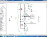
In this pic you have crossed two 1K resistors?

And also I want to ask that should I place a bypass capacitor (shown in orange-yellowish color) at the node of diodes to the ground? see attachment What I mean.

And during DC analysis I have to use only circuits before capacitors. Right? I mean the circuit in green box is only included in DC analysis not anything outside this circuit.

1)R3=1K
2)R6=1K
3)Two diodes
4)Two transistors
5)R4=1K
6)R1=1K
7)Two DC supplies

Only these 7 things will be included in DC analysis right?

And kindly tell me in DC analysis what value of resistors should I use 1K or 100K? Because you have crossed two resistors and marked values 100K, you didn't crossed all resistors. Why did you crossed two? That's why I am asking resistors values to use in DC analysis.

- - - Updated - - -

Hi again. Thanks for help and reply.

In this pic you have crossed two 1K resistors?

And also I want to ask that should I place a bypass capacitor (shown in orange-yellowish color) at the node of diodes to the ground? see attachment What I mean.

And during DC analysis I have to use only circuits before capacitors. Right? I mean the circuit in green box is only included in DC analysis not anything outside this circuit.

1)R3=1K
2)R6=1K
3)Two diodes
4)Two transistors
5)R4=1K
6)R1=1K
7)Two DC supplies

Only these 7 things will be included in DC analysis right?

And kindly tell me in DC analysis what value of resistors should I use 1K or 100K? Because you have crossed two resistors and marked values 100K, you didn't crossed all resistors. Why did you crossed two? That's why I am asking resistors values to use in DC analysis.
 

Attachments

  • 98_1339267918.jpg
    98_1339267918.jpg
    212.5 KB · Views: 78

Shayaan , is that a by pass capacitor ? of course not ! it is a coupling capacitor to restrict DC . And a note regarding bias resistors , those resistors has effect on input impedance but because the preceding stage is an op amp there won't be any problem . and those resistors can be selected lower that that
 

Oh you mean capacitor in yellow color is the coupling capacitor? And I can use 1K resistor?

Also kindly tell me the circuit in green box is the only circuit which is included in DC analysis. Right?

And I have read all your and godfreyl post. Thanks they are very useful. Thank you goldsmith and godfreyl. You both are experts.
 

shayaan , don't forget that an important thing in each amplifier is DC voltage . just consider that those diodes are short circuit instead of your signal because they are biased . so decrease the value of resistors until 20k ohms . and use two capacitor in parallel with the resistors in your base ( series with input voltage ) . and increase your voltage ( supply up to 65 volts or higher )
BTW ; did you understand what i told ? ( about to increase the supply voltage ?)
 

No. I didn't get anything. Not even a point.

Kindly provide me circuit for which I could do DC analysis and determine Q-point.
 

Humm . do you know that this circuit doesn't need give you currents more than some milliamperes ? if you know tell me the reason
 

No no no. I don't know this. I am not an experienced. I am a student still and its my first project. So I can't say anything.

Kindly you spread light on this statement.
 

you forgot things that i told you at past ? because this stage should provide enough voltage gain and current gain is up to the other stage in CC arrangement . ok ?
 

Status
Not open for further replies.

Similar threads

Part and Inventory Search

Welcome to EDABoard.com

Sponsor

Back
Top