Continue to Site

Welcome to EDAboard.com

Welcome to our site! EDAboard.com is an international Electronics Discussion Forum focused on EDA software, circuits, schematics, books, theory, papers, asic, pld, 8051, DSP, Network, RF, Analog Design, PCB, Service Manuals... and a whole lot more! To participate you need to register. Registration is free. Click here to register now.

Audio Amplifier. Which class should I use?

Status
Not open for further replies.
No I don't forget anything. But actually when you ask me I just get confused what to say. Yes it is CB complementary for high voltage gain but unity current gain. Right.
So when you ask and I couldn't answer then just understand I am confused.

So now we have completed our this CB complementary stage fully?

- - - Updated - - -

No I don't forget anything. But actually when you ask me I just get confused what to say. Yes it is CB complementary for high voltage gain but unity current gain. Right.
So when you ask and I couldn't answer then just understand I am confused.

So now we have completed our this CB complementary stage fully?
 

Hi again
So let me talk about most important think in audio amplifier design . power supply ! what is your decision about power supply ? do you have any transformer ? anywhere i don't suggest you a transformer and a rectifier and then a regulator . i want suggest you an SMPS . it can provide +-60volts ( with ability of 0.5A ) and +-50volts or higher with ability of more than 10amperes . are you familiar with SMPS ? if no , i like to educate you about them , thus you will hit to 3 point ! a first one learning about amplifiers and 2nd one is learning about SMPS and 3rd one : you'll have a good audio amplifier in your home .
Best Wishes
Goldsmith
 

Is hit to the point ! +-60 volts . but is that a waste ? this stage doesn't need high currents ( can't exceed from some milliampere ). so a voltage multiplier can supply it . aren't you agree with me ?
No, I don't agree. I think it is a waste of parts and money to make a voltage multiplier when it is not needed.

i have used this way ( multiplier ) for many times in my designs .
Why? Don't you know how to make an amplifier that can give +-30V output with +-35V rails? It is very easy! Even a simple one transistor CE stage can do the job! that is what most real amplifiers use.

- - - Updated - - -

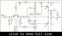
Here is an example. The CE transistor that drives the output stage is circled in red. The output voltage at it's collector can swing all the way from the positive supply voltage to the negative supply voltage.

Perhaps you recognize the circuit? It is from one of the PDFs I showed you a week ago in this thread: https://www.edaboard.com/threads/254358/.


Hi
godfreyl
of course i know how to make an amplifier with high voltages . ( however , if i want design an amplifier with high powers , i will use class D amp , but here i prefer to talk about class AB ) is price of two diode and two capacitor , high in your idea ? it's price is pretty low , of course . the circuit that you attached is good too but i think you will have some problems to educate how to design it , to shayaan . my aim is starting with simplest things . ( easy to understand for a beginner ) . but if you have simple way to educate how to design it , to shayaan , no problem . you can start !
 

The voltage amplification stage has only one transistor, but you think it is too complicated to teach?

Your voltage amplifier has two transistors, two diodes, four capacitors, and needs voltage multipliers, but you think that is simpler?

If you like, I can show how to make a simple complimentary voltage amplifier that does not need voltage multipliers.
 

i know how to do that , but my mean by complicated was not the number of transistors . i referred to how to calculate feed back loop for it and how to calculate it because it is DC coupling . i know how to calculate it . but i hope that you be able to teach shayaan , as well .
BTW : if you want i can show you my circuit ?

- - - Updated - - -

ok , now i leave this thread to your capable hands . good luck
 
Last edited:

BTW : if you want i can show you my circuit ?
Yes, I would be interested to see it. Thank you.

I understood that you want to use an opamp to increase the signal to about +-10V. Then you want to use a complimentary CE amplifier to increase the signal further to about +-30V.

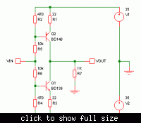
So I expected you would use a circuit like this one below. It is simply two CE stages with their outputs connected together. Is this what you had in mind?


I used this :
CE comp amp.JPG
But i wanted that shayaan understand the problem with himself . it is way to learn .he should be able to find problems in design process .

- - - Updated - - -

i measured the out put of my circuit at time =10seconds . it was a good sine wave .
 

Ah, it is similar. We think alike.

But i wanted that shayaan understand the problem with himself . it is way to learn .he should be able to find problems in design process .
This is a good idea. He must learn to find the problems in a design.

- - - Updated - - -

i measured the out put of my circuit at time =10seconds . it was a good sine wave .
Yes, that is not a problem with this circuit.
 
Last edited:

Hi goldsmith and godfeyl.

First of all I thank you for all this conversation. I want both of you to help me. But kindly let me follow only one of you so that no trouble with me.

I know SMPS stand for switched mode power supplies. I only know its abbreviation nothing more than it. So, You have to teach me it from basic.

Well But I have some questions about my design. If you let me to ask it from you (goldsmith) either godfreyl

Thanks once again you both are great electronics engineer.
 

Humm no problem , but before that tell me , what do you know about SMPS , exactly , thus we can start to educate you .
 

Information about SMPS I know are:
1) abbreviation :)
2) they are also used in PCs.

Just two things.
 

Well . i should write somethings from basic for you . and i should attach them . as soon as possible .
Best Wishes
Goldsmith
 

And what is that question ? are we oracles in your idea ? ? how we can answer your question without knowing it ?

- - - Updated - - -

BTW : do you know any thing about average value of a square wave ? ( i'm talking about way to calculate it ! ) .
 

Questions:

Q#1) It is the audio amplifier. It has 3 stages as godfreyl posted its block diagram in post#38. So we are working on its first stage. Right? If so then how much work has been left to do in it?

Q#2) We have made a circuit for voltage gain. Now we need a circuit for current gain. Right? So these two circuits are part of separate stages or they are the part of one stage?

I have some more question. But When I recall them in my memory then I will post. Please answer them.

- - - Updated - - -

The average value (I think also known as DC value) of sine wave is 0v. Right?

And I think I can calculate the average value of sine wave.

But don't know about square wave.

BTW: why did you suddenly come across the word square wave?
 

Hi shayaan . of course you'll need CC complementary stage . can you design it ? do you know rules of design for it ? ( don't worry it is pretty simple ! ) . you designed a preamplifier with opamp and then a middle stage amp and then you have to design a power amp ( current amplifier ) ok ? thus it seems your circuit is completed . but of course main section will be power supply .before that you be able to design an SMPS for that you should test it , with a simple PSU to be sure from it's behavior . do you have any PSU for primary tests ?

- - - Updated - - -

BTW: why did you suddenly come across the word square wave?
Ha ha ! of course not for fun ! let me tell you how to calculate it , after that you'll understand my meaning !
See thif formula : 1/T integral over F(T) dt from t1 up to t2 . ok ? this formula can be used for all of the functions . so with these considerations can you calculate it ?
 

Thanks for great reply,

So you mean we have designed a preamplifier (CB complementary) and now we will have to design middle stage amplifier (CC complementary stage) and then we will ave to design power amplifier. Right?

PSU (power supply unit) is the computer power supply. Right? But then SMPS are also complementary power supplies. Then what is the difference between them? I am completely confused between these two. Kindly differentiate them briefly.

And thanks I have noted down formula to calculate average value sir.
 

Oh what happened ? are you confused ? your preamplifier is opamp . did you read my latest post exactly ? when i told that my mean by PSU is computer power ?! what do you mean by complementary powers supply ?
by the way , what is the average of square wave ? could you calculate it ?
 

Status
Not open for further replies.

Similar threads

Part and Inventory Search

Welcome to EDABoard.com

Sponsor

Back
Top