goldsmith
Advanced Member level 6

- Joined
- Dec 14, 2010
- Messages
- 3,981
- Helped
- 741
- Reputation
- 1,486
- Reaction score
- 726
- Trophy points
- 1,413
- Location
- Tehran - IRAN
- Activity points
- 24,546
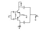
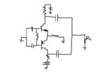
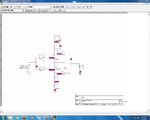
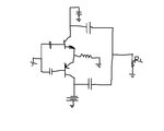
shayaan . do you want to create a class B amplifier or AB ? of course AB . so what is the condition of class AB ?
- - - Updated - - -
- - - Updated - - -
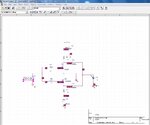
You can change it's place ! series with out put of each transistor ! did you get the idea ?But this is a coupling capacitor. If I don't use it then DC voltage will make disturbance with next stage or I will get shifted output. Isn't it?


") Here is 3:24AM
Here is 3:24AM