Continue to Site

Welcome to EDAboard.com

Welcome to our site! EDAboard.com is an international Electronics Discussion Forum focused on EDA software, circuits, schematics, books, theory, papers, asic, pld, 8051, DSP, Network, RF, Analog Design, PCB, Service Manuals... and a whole lot more! To participate you need to register. Registration is free. Click here to register now.

Audio Amplifier. Which class should I use?

Status
Not open for further replies.
I can give you the answer , simply , but i think if you try to use your maximum power to think on it , this can help you in better way !
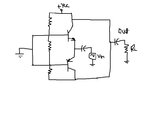
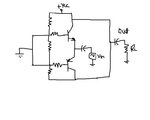
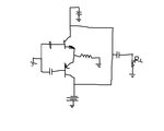
Prevent to connect bases together without any resistor ! you should use two resistors ! don't forget that this stage shouldn't give you high currents . this stage is just a voltage driver , and the main current amplification is up to , the next stage . so if the value of resistors be high there won't be any problem !
 

In order to make complementary I have to use one npn and other is pnp transistor. Is it so?
 

OK Wait please. Until I am drawing a rough schematic. Then attach it here.

- - - Updated - - -

Here is a rough sketch.

As I know CB has output at collector so I have tried to do it in sketch. And input at emitter so I have tried to do it in sketch.

Now tell how much I have successful in this exam?

- - - Updated - - -

sir goldsmith
 

Attachments

  • CB complementary.jpg
    CB complementary.jpg
    32.7 KB · Views: 69

In that picture the two bases are connected together, and the two collectors are connected together, and the two emitters are connected together.

That does not seem like a good idea. Have you thought about it some more?

Remember, the power supply will have three wires: ground, +35V and -35V. The output must be able to swing anywhere between +28V and -28V. Now you need to find where to put the two transistors so that this is possible.
 
Last edited:

But sir godfreyl Common-Base configuration have input at its emitter and output at its collector. That's Why I connected emitter together and provide input, connected collector together and taking output and finally in Common-Base we have base is grounded so as I did.

What is mistake?

- - - Updated - - -

Dear godfreyl. Help me I want to learn this.
 

Hi shayaan . of course your circuit isn't correct . let me show you an example . for CE ( half wave . ) thus perhaps you can correct your one ! see below , please :
Circuit for shayaan.JPG
circuit for shayyan 2.JPG
Best Wishes
Goldsmith
 

goldsmith Why did you use inductor and diode in your voltage divider?
 

it is optional . ( to use or not ) but in fact i used it to prevent the clipping ! because the npn transistor will work with positive polarity !
 

What is mistake?

Look again at your circuit. The output is connected directly to the +supply, and the -supply is not connected anywhere. That can't be good.

But now forget about that for a moment (or imagine we fixed it) and think about this:
  • The base of the top transistor is connected to ground.
  • The emitter can not be more than 0.7V below the base, so the input can not be lower than -0.7V.
  • The collector can not be more than 0.7V below the base, so the output can not be lower than -0.7V.
and also this:
  • The base of the bottom transistor is connected to ground.
  • The emitter can not be more than 0.7V above the base, so the input can not be higher than +0.7V.
  • The collector can not be more than 0.7V above the base, so the output can not be higher than +0.7V.

Remember what Goldsmith said in post 122 about connecting things together with resistors. That is the secret. ;-)
 

OK. So I should modify this diagram with complementary . Then if I successful in it then I should do this same with CB. Right?

- - - Updated - - -

godfreyl You mean this should be look like this?

Attachment.

- - - Updated - - -

godfreyl Everything What you have said to me about base in post#131 I have understood. And yes you are right.
 

Attachments

  • CB complementary.jpg
    CB complementary.jpg
    34.5 KB · Views: 62

In post#128 goldsmith provide me CE. So now I have make its complementary. Kindly take a look. Don't make any mistake about any component that I have not places correctly. You just check is this complementary CE looks like?
If it is right then you can tell me about components that you don't place a resistor there etc etc...

I hope you can understand.

Thanks to both goldsmith godfreyl
 

I have a better suggestion ! test it with your simulator ! with random values of components ! and show us the result . i know what will happen , but it is pretty important that you simulate each section of your project . it will help you for your future .
 

Here is attachment.
 

Attachments

  • CE complementary.jpg
    CE complementary.jpg
    26.6 KB · Views: 64

Everything What you have said to me about base in post#131 I have understood.
OK, now think about the NPN transistor first. You want to make a common base amplifier, correct? That means the base is at a fixed voltage and output is from the collector.

We know that the output must go all the way from +28V down to -28V, so the collector must also do that. But we also know that the collector can not go more than 0.7V below the base. So what voltage must the base be fixed at?

If you get that answer, and think the same way about the PNP transistor, then you can start to draw the circuit.

edit: Goldsmith's idea is good - you should test each circuit in the simulator.
 

I have a better suggestion ! test it with your simulator ! with random values of components ! and show us the result . i know what will happen , but it is pretty important that you simulate each section of your project . it will help you for your future .

I know you are helping me thoroughly. But I don't know what result should I get if I simulate my circuit. If there was any error then I am not able to troubleshoot or even catch it. Therefore, at each step I am taking your guidance. Because in university they never ever taught us to troubleshoot anything.
 

Shayaan . why you used a series capacitor with your load ? your supply voltage is simultaneous , and you won't need capacitor . for it !

- - - Updated - - -

Humm , as i suggested , bring us the result , we will tell you that is that correct or no .
 

BTW : pay attention to the latest thing that Godfreyl told about voltages , it is pretty important .
 

OK, now think about the NPN transistor first. You want to make a common base amplifier, correct?

Yes.

We know that the output must go all the way from +28V down to -28V, so the collector must also do that. But we also know that the collector can not go more than 0.7V below the base. So what voltage must the base be fixed at?[\quote]

So its mean base should not be ground. Base must be at some potential. I think must be positive potential.

- - - Updated - - -

Shayaan . why you used a series capacitor with your load ? your supply voltage is simultaneous , and you won't need capacitor . for it !

But this is a coupling capacitor. If I don't use it then DC voltage will make disturbance with next stage or I will get shifted output. Isn't it?
 

Status
Not open for further replies.

Similar threads

Part and Inventory Search

Welcome to EDABoard.com

Sponsor

Back
Top