Shayaan_Mustafa
Full Member level 5

Follow along with the video below to see how to install our site as a web app on your home screen.
Note: This feature may not be available in some browsers.


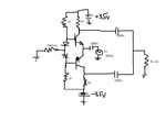
Before you do that, did you notice that there is a very big problem with this circuit posted by Goldsmith. If you build this circuit, it will not work as you expect.Now I will convert it to CB and then post result.
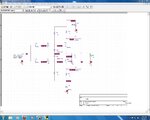
Hi GodfreylIn your simulation, look at the current flowing through C9 or C10. Do you see that the current is flowing mostly (or only) in one direction? That means the capacitors are slowly discharging.

Hit to the point !Oh OK OK.. I got. So you mean CB is to provide high voltage gain and CC is to provide high current gain.
Right?
No, it is not important. But if you look at it, you may learn something. If you look at it, you may understand why there is a problem.What is the benefit of current through , Capacitors ? are those really important ? of course no .
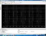
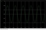
Yes, this if most important. Did you look at the output waveform for 5 or 10 seconds to see what happens?we are just looking for out put waveform ( voltage across the load ) .
The music will become very distorted. That is special. I think Shayaan will want to listen to music for longer than 2 seconds.And if you think this circuit after some second will cut the waveform , what will happen ? nothing special !
The things I said are important.though we can say , things that you told are not important for our signal amplification .
of course i want . but you forgot to answer my question ! why in a CE class A amplifier you didn't say that ! is there any path to discharge the capacitor ? of course no ! if we use two stage as a chain , adn the other stage with Zi = pretty high .Do you not want to learn anything?
Quite right . but i didn't say that to shayaan because i wanted that he understand this issue that the specifications of transistor are pretty important . such as HFE and VCE and IC and vcesat and vbe ( reverse ) . and GBWP of current . and ....Did you look at the voltage on the transistor collectors? If you do you will see that there can be more than 60V between the collector and emitter. So why do you use BD135 and BD136? They are only rated for 45V. BD139 and BD140 would be better.