Continue to Site

Welcome to EDAboard.com

Welcome to our site! EDAboard.com is an international Electronics Discussion Forum focused on EDA software, circuits, schematics, books, theory, papers, asic, pld, 8051, DSP, Network, RF, Analog Design, PCB, Service Manuals... and a whole lot more! To participate you need to register. Registration is free. Click here to register now.

[PIC] Power factor measurement using PIC18f4520

Status
Not open for further replies.
Ok. Added a 10k load. Checked with and without a ground to VSIN model.

Does this mean that OP has designed the circuits such a way that one has to use a 2.0V Vref for the ADC ?

- - - Updated - - -

Used a transformer for checking. I am attaching the Proteus 8.3 SP2 format file.
 

Attachments

  • VMC Rev1.png
    VMC Rev1.png
    81.5 KB · Views: 108
  • VMC Rev2.png
    VMC Rev2.png
    71.5 KB · Views: 107
  • Voltage measurement Rev2.rar
    15.7 KB · Views: 97
  • VMC Rev3.png
    VMC Rev3.png
    113.8 KB · Views: 116

I do not have Proteus but I would guess the reason for the strange voltages is the time constant of the filter, it would take several AC cycles for the voltage to settle and maybe you are not allowing enough time.

I would not advise the ADC reference was switched to an external source, especially between one reading and another. If the proportions of R1 and R2 are chosen wisely, the voltage can be made closer to 5V although I would aim for a little less to allow a safety margin. The readings on the 'Rev3' should not be taken as true, they depend on where the oscilloscope ground is connected and channel A uses a different reference to the other channels. If the ground is (correctly) set at the negative side of the capacitors Channel B should show a half sine wave because D3 rectifies the signal.

Khaled, I will do my best to write some Oshonsoft code for you and post it later today. You may have to change some numbers as there is no way I can test with real hardware here.

Brian.
 
For most accurate readings I would suggest using 74AC86 or 74ACT86 because the 'S' version has bipolar transistor outputs which may not exactly reach 0V and 5V at the output pin.

Program to try and the data sheet attached.

Note that the ADC inputs voltage, current and phase are on pins AN0, AN1 and AN2 respectively. (PORTA 0,1 and 2).

Brian.

Code:
Define LCD_LINES = 4
Define LCD_CHARS = 16
Define LCD_BITS = 8  'allowed values are 4 and 8 - the number of data interface lines
Define LCD_DREG = PORTC
Define LCD_DBIT = 0  '0 or 4 for 4-bit interface, ignored for 8-bit interface
Define LCD_RSREG = PORTD
Define LCD_RSBIT = 0
Define LCD_EREG = PORTD
Define LCD_EBIT = 2
Define LCD_RWREG = PORTD  'set to 0 if not used, 0 is default
Define LCD_RWBIT = 1  'set to 0 if not used, 0 is default
Define LCD_COMMANDUS = 2000  'delay after LCDCMDOUT, default value is 5000
Define LCD_DATAUS = 100  'delay after LCDOUT, default value is 100
Define LCD_INITMS = 100  'delay used by LCDINIT, default value is 100
'the last three Define directives set the values suitable for simulation; they should be omitted for a real device

Dim v_divider As Single
Dim i_divider As Single
Dim p_divider As Single
Dim display_value As Single

v_divider = 4.092  'scaled so 1023 = 250V
i_divider = 102.3  'scaled so 1023 = 10A
p_divider = 5.688  'scaled so 512 = 2.5V = 90 degrees


Dim voltage As Word
Dim current As Word
Dim phase As Word

Lcdinit 0  'initialize LCD module; cursor is blinking
TRISA = 0x07  'TRISA has bits 0,1 And 2 As inputs
ADCON1 = 0x0c

main:

ADCON0 = 1

loop:
Adcin 0, voltage  '1023 = 5V at ADC input pins
Adcin 1, current
Adcin 2, phase

Lcdcmdout LcdLine1Home
Lcdout "Voltage="
display_value = voltage / v_divider
Lcdout #display_value

Lcdcmdout LcdLine2Home
Lcdout "Current="
display_value = current / i_divider
Lcdout #display_value

Lcdcmdout LcdLine3Home
Lcdout "Power="
display_value = (voltage / v_divider) * (current / i_divider)
Lcdout #display_value

Lcdcmdout LcdLine4Home
Lcdout "Phase="
display_value = phase / p_divider
Lcdout #display_value

Goto loop

End
 

Attachments

  • mc74ac86.pdf
    87.9 KB · Views: 90
Hello,

Dear Brian, the XOR circuit with the HD74S86 has a serious problem:

Once I connected it just as I've uploaded previously its image, with a 100K instead of two 470K, and by feeding the XOR chip from the same +5V 0 of PIC rails, the PIC also the LCD went not working! Suddenly no LCD are there, as if the system stops functioning.

When I've detached the XOR circuit from the system, the PIC as well as the LCD as well as the entire circuits went back to normal and re-functioned as supposed (by showing V and I)

Why has this happened once I connected the XOR circuit?

- - - Updated - - -

I also tried to feed the HD74S86P from a 7805 Voltage regulator, and by connecting its circuit to the total ground circuit of PIC, LCD, etc...

The PIC as well as the LCD didn't stop functioning, but all the times the output of the XOR chip is of 0.192VDC, what ever the load there is, whether a 200W resistive bulb, or else the 60W fan, the output of it remains the same.

Does this mean the following:

1) I cannot feed the XOR chip from PIC's 5V rails, for an electrical reason
2) When fed from 7805 the XOR circuit worked fine, EVEN if I`m only seeing on the DVM a constant DC value of 0.192V but this cannot be checked unless seen on oscilloscope (just like when we were testing the zero crossing circuits, the value on DVM is not accurate and non changeable, it must be tested using an oscilloscope

- - - Updated - - -

Hello

I think something might have worked:

When feeding the XOR from an 7805 Voltage regulator, and branching its ground to PIC's ground (so both can communicate together) and branching its A and B inputs just as uploaded and branching its output after a double RC-RC circuit, to one of PIC's analog input, the results were as following:

Code:
 Adcin 2, phase
          Lcdout "Phase: ",#phase

In the case of 200W resistive lamp: Phase = 21
In the case of 60W fan: Phase = 82
 

The 74S86 has a maximum current consumption of 75mA which is very high, if you can find a 74AC86 it is typically 5uA, some 15,000 times less so I would guess your power source couldn't handle the extra load. The 'AC' version also has better output levels, with a light load it goes closer to 0V when low and nearer to 5V when high so it will give a better linearity in the phase measurement, especially near to 0 degrees.

The readings are encouraging, remember that there is an additional phase shift in both the voltage and current inputs caused by the transformers so it is reasonable to expect some residual readings. The transformers introduce a fixed shift so it is safe to remove it in software. If you change the phase calculation to subtract 21 it should compensate for the transformers and then give good results.

Your product is basically working but there is still one more issue you may want to look at - it doesn't tell you whether the phase shift is inductive or capacitive, it only shows there is a difference.

Brian.
 
@betwixt

In your OshonSoft code no need to disable Comparators ?
 

The 74S86 has a maximum current consumption of 75mA which is very high, if you can find a 74AC86 it is typically 5uA, some 15,000 times less so I would guess your power source couldn't handle the extra load. The 'AC' version also has better output levels, with a light load it goes closer to 0V when low and nearer to 5V when high so it will give a better linearity in the phase measurement, especially near to 0 degrees.

The readings are encouraging, remember that there is an additional phase shift in both the voltage and current inputs caused by the transformers so it is reasonable to expect some residual readings. The transformers introduce a fixed shift so it is safe to remove it in software. If you change the phase calculation to subtract 21 it should compensate for the transformers and then give good results.

Your product is basically working but there is still one more issue you may want to look at - it doesn't tell you whether the phase shift is inductive or capacitive, it only shows there is a difference.

Brian.

Dear Brian:

There is a problem with the "fudge factor"

Also there is a problem with Cos() function in Oshonsoft :(

Non correct values of cosine for resultant phase angle are taking place.

I will post the fudge factor that ive detect it, also the numbers of samples per cycle for ADC measures.

Once I have a PC access i will post schematic.

Meanwhile are there any solutions for Cos function in oshonsoft?
 

It doesn't say anywhere in the documentation about cos() which units it uses so I wrote a small program to check for myself. The parameter is expected n radians so you would have to divide the result by 57.295 (360/(2*pi)) to convert the result. Alternatively, change the p_divider to 325.894 to convert the ADC result directly to radians then take cos() of the result.

Brian.
 
Hello, and thanks again:

I`m sorry that a user cannot vote for more than three helped me per day. You've given more than I deserve.

Here's the final of what we've been up to:

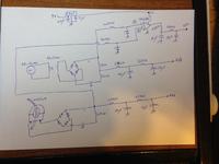
Following is the analog schematic for V, I, P, and Phase angle measurement using PIC18F4520:


Notes about the total P,V,I,pf circuit:
1) I've fed the 74S86 from another supply voltage than the PIC's supply, since it consumes too much power and affect PIC as well as LCD functioning.
2) I've connected a 10K resistor as a burden for CT, because at this level, the maximum load I want to test is of 1A


The following is the CODE for the above attached image, using cursed Oshonsoft compiler:

Code:
ASM:        org 0x800
Define LCD_LINES = 4
Define LCD_CHARS = 16
Define LCD_BITS = 8  
Define LCD_DREG = PORTC
Define LCD_DBIT = 0 
Define LCD_RSREG = PORTD
Define LCD_RSBIT = 0
Define LCD_EREG = PORTD
Define LCD_EBIT = 2
Define LCD_RWREG = PORTD  
Define LCD_RWBIT = 1  
Define LCD_COMMANDUS = 2000  
Define LCD_DATAUS = 100  
Define LCD_INITMS = 100  
Define ADC_SAMPLEUS = 255 //This command makes more samples per cycle, and without it no ADC will be accurate

Lcdinit 0  
ADCON1 = 0
Dim volt As Word
Dim x As Single
Dim current As Word
Dim y As Single
Dim pow As Single
Dim phase As Word
Dim phasean As Single
Dim currentan As Single
Dim currentan2 As Single
Dim allcurrent As Single
Dim flag As Word                //So sorry for using TOOO much variables, I know this is a sign of stupidity 
Dim fudgefactor As Single
Dim pf As Single

Dim vcounter As Word
Dim icounter As Word
icounter = 30
vcounter = 5
x = 0
y = 0
pf = 0
fudgefactor = 8.192 //When 74S86 is interfaced to the total system, even when no load is there, it showed a 0.035 as a maximum value for amperes, so I've to limit it by subtracting the current from this value; I got it from: 0.04*1024/5
phase = 0


main:
Lcdcmdout LcdClear
Lcdout "Processing..."
WaitMs 300
Lcdcmdout LcdLine2Home
Lcdout "Testing System"
WaitMs 300
Lcdcmdout LcdLine3Home
Lcdout "Checking Inputs"

While vcounter > 0
Adcin 3, volt

x = x + volt
vcounter = vcounter - 1          //This is to test the values for adc of measured voltage 5 times, for more accuracy
volt = 0
Wend

x = x / 5
x = x * 5 / 1024
x = x * (1510 / 510)
x = x + 1
x = x * 16.30  //I`m having trouble in outputting real input voltage value, I think that this is done due to two things: sometimes the supply voltage can reach to 230V instead of 220V, and the 220/12VAC transformer does not have a fixed turns ratio 'n' so the value "16.30" is often changed, and sometimes present; sometimes the supply voltage is 230VAC but it shows after this conversion on LCD a "255.5VAC" value. [I]HOW to eliminate this error, is it by hardware, or software implementation?[/I]


Lcdcmdout LcdClear
Lcdout "Vinput: ", #x, "V"

currentloop:
While icounter > 0          //Here starts the adc measurement of current, thirty times
Adcin 1, current
   
    y = y + current
    icounter = icounter - 1
        current = 0
    Wend

    y = y / 30              //The results of current measurement are very acceptable!
    WaitMs 1500
   
    If fudgefactor > y Then    //due to [I]fudge factor[/I] introduced by 74S86, I must check if no load is there by this comparision method, such that if there is any value below 0.04Amps in reality, consider it as no load.
        Goto noload
    Endif
   
    currentan = y * 5 / 1024


If y = 0 Then
noload:
    flag = 0
    Lcdcmdout LcdLine2Home
    Lcdout "I: 0 A"
    Lcdcmdout LcdLine3Home
    Lcdout "Power = 0W"                  //These are the results when having no load, and they're true
    Lcdcmdout LcdLine4Home
    Lcdout "Phase: NO LOAD"
    Goto prog_end
Else
    flag = 1
    currentan2 = currentan + 0.063
    allcurrent = currentan2 * 0.2
Lcdcmdout LcdLine2Home
Lcdout "I(load)= ", #allcurrent, "A"
Endif

WaitMs 1000
       
If flag = 1 Then
    Lcdcmdout LcdLine3Home
    pow = allcurrent * x
    Lcdout "Power: ", #pow, "W"         //These are the results when there is a load connected
    WaitMs 1000


    Adcin 2, phase       //Here starts the adc measurement of XOR circuit output
    Lcdcmdout LcdLine4Home
    phasean = phase / 1.6     //I've got the number '1.6' when connecting the fan load, the phase angle showed was almost 82, and cos(82) is almost 0.14 which is not logical, instead, such loads have a typical 50degrees phase angle value, so 82/50 almost 1.6
    Lcdout "Phase: ", #phasean
    WaitMs 2000
    phasean = phasean / 325.894
    Lcdcmdout LcdLine4Clear
    pf = Cos(phasean)          //applying cosine for the radians to degrees transformed 'phasean'
    Lcdout "pf: ", #pf
    WaitMs 1000
    Endif

prog_end:
End

What I ask for is the following:

1. How to make voltage reading [whether by hardware/software/both more stable and accurate
2. How to fix the Cos() function in Oshonsoft compiler

The cosine after the code that I've posted, is almost stable for all loads, at 0.995 or 0.993 for the 200W light bulb, as well as the 60W fan. This is not true, and I hope we can solve this.


Thank you!!
 

Hi,

1. How to make voltage reading [whether by hardware/software/both more stable and accurate
First you have to discover where the error is. Can you see the instabilities with a DVM. Or is it stable?

If the analog value is stable, then the problem is on the microcontroller side. Either Vref or GND (maybe VCC) is fluctuating, the ADC timing is wrong, or the value is processed wrongly.

Klaus
 
Your product is basically working but there is still one more issue you may want to look at - it doesn't tell you whether the phase shift is inductive or capacitive, it only shows there is a difference..

It is impossible to determine the sign of phi (the phase shift) from these measurements as cos(+phi) is same as cos(-phi). You need to look at the waveforms and decide. To do that, you need to compare the voltages and currents in quarter wave-forms.
 
Hello,

I`ve made a test to determine Oshonsoft cos() output code, and the results were same as betwixt concluded, it proceeds the cosine value in Radians.

I've made the following:
Code:
y = 60
cosy = Cos(6)
Lcdout "Cos(60) = " , #cosy

The result was: -0.952 << This is the identical result of making the cosine of angle 60 In radians.

Since I want the result in degrees, I've made the following: Transforming degree angle to radians and having its cosine.

For example: 60 in degrees is same as 60 * pi/180 in radians, where pi/180 can be noted for a Single variable as: "0.0174539"

So, Cos(60) in degrees have the value of 0.5 and using Oshonsoft the 60 degree must be multiplied by "0.0174539" where also same result as in degrees take place.

Cos() function problem is solved

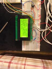
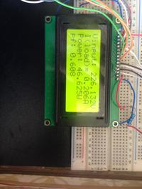
I've tested the system for the 200W light bulb, this is the observation on LCD:


I've tested the system for the 60W fan, this is the observation on LCD:


So far, the most accurate ADC measurement is the current measurement [thanks to KlausST circuit improvment]
but there is problems with ADC measurement of Voltage, as well as the phase:

the V value shown on LCD, fluctuate from 216VAC to 225VAC when real supply voltage is around 220VAC
the phase shownn on LCD, also fluctuate from 35 to 50 degrees for the 60W fan load.


How to make these two non-accurate ADC measurements more precise?

The 220VAC to 12VAC voltage transformer could sometimes be applied to a 230VAC supply, instead of 220VAC, so its ratio number is not precise for all time. Maybe this is the only problem?
Here is the ADC code for voltage measurement:

Code:
vcounter = 30
While vcounter > 0
Adcin 3, volt

x = x + volt
vcounter = vcounter - 1
volt = 0
Wend

x = x / 30                     //This is because the adc value is accumulated 30 times
x = x * 5 / 1024            //This is to get back the voltage corresponding to the 0-1024 10-bit digital input
x = x * (1510 / 510)      //This is to get back the initial voltage, before resistive voltage divider value
x = x + 0.5                  //This is due to diode voltage drop, in the rectifier after the transformer
x = x * 16.30              //This is the turns ratio 'n' of the voltage transformer that often changes from 16.25 to 16.4
                                  and I think that this has a big portion of problem creation

Lcdcmdout LcdClear
Lcdout "Vinput: ", #x, "V"  //This is to send the resultant voltage, to LCD

Also for the phase angle measurement, it is fluctuating but reasonably here is its ADC code measurement:
Code:
    Adcin 2, phase
    Lcdcmdout LcdLine4Home
    phasean = phase / 1.6
    Lcdout "Phase: ", #phasean
    WaitMs 2000
    phasedeg = phasean * 0.01745329
    Lcdcmdout LcdLine4Clear
    pf = Cos(phasedeg)
    Lcdout "pf: ", #pf
    WaitMs 1000
    Endif

Should I make same as v adc, get its value like 30 times to be more accurate? are there any hardware changes that must be done?

I would like to hear from you the stability of this system, should I begin soldering it or it needs more tests and modifications, according to betwixt "Sometimes a bad circuit takes time to crash, will this crashes?

Thank you
 

Hello,

The problem of accurate cos(phi) is also solved:

When the load initially turns on, it enters a transient state, that I guess it would affect XOR output.

To get an accurate phase angle, only place a bit long delay before Adcin 2,phase such that you will have enough time for the load to enter its steady-state.

I believe that this project is half-done.

I`m into the next part of this project:

First of all, since all V, I P, cos(phi) are known, I want to tell the user, if he wish to continue he please presses the push-button.

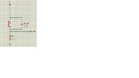
This is not a problem, what I`m asking about is the RC de-bouncing circuit for such types of push-buttons:


It is rated at 10A, will the following de-bouncing circuit helps:


Thanks
 

Hi,

The circuit is simple.
But it is unsymmetric:
When the button is pressed an incalculable high current discharges the capacitor immediately. The voltage at the port pin rises extremely fast. The high current pulse causes EMI.
When the button is released the capacitor is charged ... slowly ...with the resistor. The voltage at the port pin falls slowly.

I'd use an additional series resistor, may be 4k7.
Push button and your 1k is connected like in your curcuit. Then the series resistor to the port pin.
The capacitor instead at pushbutton --> directely to the port pin.

Klaus
 
Well done!

You could try increasing the ADC sampling time to improve accuracy. I can't guarantee it will help but if you switch channels too quickly, some of the previous charge on the sample and hold capacitor can remain and cause a wrong reading. You can check it by increasing the "Define ADC_SAMPLEUS =" setting. Typically when the value is too low for the selected conversion speed, you start to see some interaction between the voltages measured at the inputs, for example, if AN0 increases and the next channel you select is AN1, you see an increase in that too.

The debounce may be adequate but I would increase the resistor to 10K and wire a 1uF capacitor across it, also add 100 Ohms in series with the switch so it's contacts are protected against charging and discharging current. The input pins of the PIC only need a tiny current so it is quite in order to use larger value resistors for pull-up and pull-down. How much debounce time you need will depend on how rapidly your software reads the switch input again and of course the actual contact bouncing time. You might be able to get away with just adding a delay of say 1mS after detecting the switch is closed or opened.

Brian.

Hello Brian and thank you

What causes PIC not to detect a button once pushed?
As you see in the attached image of debouncing circuit, its connected using a pull-up resistor, so when pressed the pic must detect a high logic on that pin.

I've connected the output of switch to portb.0 and coded:
If PORTB.0 = 1 Then etcc

But the pic even when switched the button didnt respond, although voltage at input pin is high
I tried to longer lasting the push, also same results

Is it because of what you've told me about PIC18F4520 processors of default analog enabling state after switch on or reset?
Or?


Thanks
 

ADCON1 has to be configured and debounce delay has to be used in code.

C Code example.

Code:
if(PORTB.F0 == 1) {
     Delay_ms(80);
     while(PORTB.F0 == 1)asm clrwdt;

     //do what you want on button press here

}
 

80mS is overkill, most switches will settle in <10mS but how long is needed in the program depends on when the switch is next checked. The debounce is only important if there is a risk of the the input being read more rapidly than the contacts settle and it being seen as in the wrong state during the bounce period.

Khaled, look at table 19-2 on the data sheet, it tells you the bits you have to set in ADCON1 to make the pins analog or digital. They default to analog when the PIC is reset for safety reasons.

Brian.
 
@betwixt

I use mikroE development boards and I use 80 ms debounce delays in mikroC Code and they work fine on the hardware.
 

Status
Not open for further replies.

Part and Inventory Search

Welcome to EDABoard.com

Sponsor

Back
Top