Continue to Site

Welcome to EDAboard.com

Welcome to our site! EDAboard.com is an international Electronics Discussion Forum focused on EDA software, circuits, schematics, books, theory, papers, asic, pld, 8051, DSP, Network, RF, Analog Design, PCB, Service Manuals... and a whole lot more! To participate you need to register. Registration is free. Click here to register now.

[SOLVED] PIC complete discussion for all

Status
Not open for further replies.
Hi,
As you can see from the diagram, the 4MHz is in the input to the system and the output from the system is 48MHz (when postscaler is set to 1:2). So, you can no longer use the 4MHz clock. Now it is 48MHz.

Hope this helps.
Tahmid.
 
Hi,
As you can see from the diagram, the 4MHz is in the input to the system and the output from the system is 48MHz (when postscaler is set to 1:2). So, you can no longer use the 4MHz clock. Now it is 48MHz.

Hope this helps.
Tahmid.

yeah I get it now... but to enable the PLL is during setting of configuration bits right??

---------- Post added at 18:23 ---------- Previous post was at 18:22 ----------

check my simple code above and suggest what to improve... hehehehe thank you so much... I got confuse also in the ADC part ADRES register
 

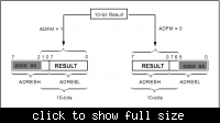
Depends on what you want. If you want an 8-bit value, then reading only ADRESH will do. If you want a 10-bit value, then use this:
Code:
adc_result = (ADRESH<<2) + (ADRESL>>6);

This is all using left-justification.

I hope you understand what I mean. If not, I'll try to help make you understand.

Hope this helps.
Tahmid.

---------- Post added at 22:33 ---------- Previous post was at 22:31 ----------

I think this will make it clear:


Hope this helps.
Tahmid.

---------- Post added at 22:42 ---------- Previous post was at 22:33 ----------

What you wrote is also okay. But the problem is, you set PR2 to 255. So, you can't assign the ADC value directly to CCPR1L as CCPR1L is an 8-bit register.

Hope this helps.
Tahmid.
 
What you wrote is also okay. But the problem is, you set PR2 to 255. So, you can't assign the ADC value directly to CCPR1L as CCPR1L is an 8-bit register.


this bits bellow +CCPR1L register will make the PWM 10bit resolution right? but still confuse how do I write values to this LSB.
CCP1CONbits.DC1B0 |= 0;
CCP1CONbits.DC1B1 |= 0;


adc_result = (ADRESH<<2) + (ADRESL>>6);
what is the difference of using '+' with the | operator in this case?


What you wrote is also okay. But the problem is, you set PR2 to 255.
why I cannot set PR2 with 255? I think that would be the lowest frequency if the value is 255 according to the formula. right?
 

If you want to read 10bit it would probably make more sense to use right justified setting, in that case you can get the result

adc_result = (ADRESL) | ((unsigned int)(ADRESH<<8));


for the left justified setting

adc_result = (ADRESL>>6) | ((unsigned int)(ADRESH<<2));

Alex
 
Hi,
Setting PR2 to 255 isn't the problem. The problem is that, since you set PR2 to 255 and that is the maximum allowable value, the duty cycle register CCPR1L has to be assigned a value equal to (max possible) or less than 255. However, the value you received from the ADC reading that is stored in variable x can vary from 0 to 1023. You can't assign 1023 to an 8-bit register.

Hope this helps.
Tahmid.

---------- Post added at 23:00 ---------- Previous post was at 22:59 ----------

Code:
but to enable the PLL is during setting of configuration bits right??

Yea. You also have to set the PLL prescaler and the postscaler. If you check the diagram you posted in the last page, you can configure the system clock by using the prescaler and postscaler.

Hope this helps.
Tahmid.
 
DC1B0 and DC1B1 are used to set decimal places, eg for setting 220.50 in CCPR1L. The max is still 255. The 2 other bits are for precision. I have to look this up and I'll tell you more about it.

---------- Post added at 23:06 ---------- Previous post was at 23:04 ----------

Yea, it's the same. But, why would you do
Code:
ADRESH << 8
For left-justified settings, you need to do
Code:
ADRESH << 2

Hope this helps.
Tahmid.
 
DC1B0 and DC1B1 are used to set decimal places, eg for setting 220.50 in CCPR1L. The max is still 255. The 2 other bits are for precision. I have to look this up and I'll tell you more about it.

Okay,.. I thought it will make the pwm 10bit reso...
 

Yea. You also have to set the PLL prescaler and the postscaler. If you check the diagram you posted in the last page, you can configure the system clock by using the prescaler and postscaler.

If I will leave as it is the default PLL prescaller would be /1 and also the prescaller is 1/2... so I still I can get the 48Mhz clock I want...right?

---------- Post added at 19:17 ---------- Previous post was at 19:16 ----------

Hi,

Like I said before the 10-bit works like this:
8 bits for 0 to 255, 2 bits for decimal places.

So, you can't get 0 to 1023.

Hope this helps.
Tahmid.

okay thanks so much.. noted...
 

If I will leave as it is the default PLL prescaller would be /1 and also the prescaller is 1/2... so I still I can get the 48Mhz clock I want...right?

Yes, you will get the 48MHz clock.

---------- Post added at 23:20 ---------- Previous post was at 23:19 ----------

Maybe you might not need it, but you might want to read through AN594 [Using the CCP Module(s)] for revision:

https://ww1.microchip.com/downloads/en/AppNotes/00594B.PDF

---------- Post added at 23:23 ---------- Previous post was at 23:20 ----------

Woa! What just happened? Why's there 3 exact same posts?
 
i think its the same if we say

for the left justified setting
adc_result = (ADRESL>>6) | ((unsigned int)(ADRESH<<8));
with
adc_result = ((unsigned int)(ADRESH<<8)) | (ADRESL>>6);


Yes the order doesn't matter but you are shifting more positions that you should, I hope I didn't confuse you because I had it wrong when I posted my previous answer, I saw it after I posted but maybe you read the un-edited version

0b11111111<<2 results to 0b1111111100 (ADRESH)
0b11000000>>6 result to 0b00000011 (ADRESL)

0b1111111100 | 0b11 is exactly the same as 0b11 | 0b1111111100

The order doesn't matter in AND, OR etc

Alex
 

Yes, you will get the 48MHz clock.

---------- Post added at 23:20 ---------- Previous post was at 23:19 ----------

Maybe you might not need it, but you might want to read through AN594 [Using the CCP Module(s)] for revision:

https://ww1.microchip.com/downloads/en/AppNotes/00594B.PDF

Thanks so much..

I have also difficulty in using high frequecy of pwm e.g. 250KHz.. the value of PR2 register is between 1 - 2 I think.. so very difficult to give value to CCPR1L register since its value cannot be more than or the same... I think the DC1B0 and DC1B1 bits will be use this time since we are dealing with small values of duty cycle...right?
 

Yes, you can use those two bits then as they will be helpful. However, I would not be trying to do 250kHz with a PIC (8-bit ones). I'd rather do it with a PWM chip. I'd get much better accuracy.
 
Actually there is something very wrong with the forum and it is behaving very strangely, doesn't show users , doesn't show new messages and what happened to you happened to me yesterday..with one of my messages.
Your post is a single one shown three times (mine was shown two times), if I try to delete any of them they will all be deleted, they have a single post identity code.

Alex
 
forum is behaving strangely.. I cannot post right away...

i will sleep for now guys since its 2:30am here... thank you so much guys..

---------- Post added at 19:36 ---------- Previous post was at 19:35 ----------

Actually there is something very wrong with the forum and it is behaving very strangely, doesn't show users , doesn't show new messages and what happened to you happened to me yesterday..with one of my messages.
Your post is a single one shown three times (mine was shown two times), if I try to delete any of them they will all be deleted, they have a single post identity code.

yes. I experience that also
 

Status
Not open for further replies.

Similar threads

Part and Inventory Search

Welcome to EDABoard.com

Sponsor

Back
Top