Continue to Site

Welcome to EDAboard.com

Welcome to our site! EDAboard.com is an international Electronics Discussion Forum focused on EDA software, circuits, schematics, books, theory, papers, asic, pld, 8051, DSP, Network, RF, Analog Design, PCB, Service Manuals... and a whole lot more! To participate you need to register. Registration is free. Click here to register now.

Phase Angle Control Using Controller

Status
Not open for further replies.

gauravkothari23

Advanced Member level 2
Joined
Mar 21, 2015
Messages
644
Helped
5
Reputation
10
Reaction score
4
Trophy points
1,298
Visit site
Activity points
6,951
Hi all.
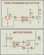
I am trying to Control the Speed of 120W AC Motor using controller NUC029LAN, Traic BT136, Zero Detection Circuit.
Have also attached the circuit diagram and some wave form. In the waveform i am triggering the Triac after 7ms delay after zero crossing is detected.
my problem is when incandescent bulb is connected as load, it works perfectly (wave form attached at 7ms of delay).
But when 120W AC motor is connected, i am not able to control the speed, it rotates at full speed only. (Wave form Attached at 7ms of Delay).
The waveform when motor is connected, is completely changed.
Have also attached the waveform of MCU Pin which is driving the Triac with reference of 12V AC, just for reference to confirm that there is no issue with the software part.
Can anybody please let me know where the issue is.
 

Attachments

  • Circuit Diagram.jpg
    Circuit Diagram.jpg
    121.2 KB · Views: 477
  • Motor-1.jpg
    Motor-1.jpg
    4.4 MB · Views: 256
  • Motor-2.jpg
    Motor-2.jpg
    4.8 MB · Views: 210
  • Motor-3.jpg
    Motor-3.jpg
    4.4 MB · Views: 267

i have already uploaded the circuit in post 1
--- Updated ---

remember the 3021 has a peak current of 1A, so a 330 ohm res needed to the gate of the main triac else you risk blowing the 3021 ( and the main triac ) when running on 230Vac

your picture above is no help as you don't show how the measurement was taken or the complete circuit. One can't even read the volts / div easily ...!

--- Updated ---

View attachment 176018
the snubber cap can be up to 100nF 375Vac rated. note the 360 ohm current limit.
have even tried adding snubber to MOC3021, but the things are not yet working
 

Attachments

  • Circuit Diagram.jpg
    Circuit Diagram.jpg
    121.2 KB · Views: 143
Last edited:

there is no way to debug your circuit ( or likely buggy software ) with such little and incomplete information.
--- Updated ---

--- Updated ---

--- Updated ---

--- Updated ---

 
Last edited:

Hi all.
Finally Done with it.
Now i am able to control the speed of the motor. and motor runs very smoothly in any speed which is required.
Thanks to all for your support.
 

Hi,
Remember "ELI the ICE man?"
This tells us that in an inductive circuit, voltage leads current. So even when the voltage has gone down to zero, the current has not. It takes some time before the current gets down to zero after the current has. In a purely inductive circuit, it takes 90 degrees.
Also, when the voltage starts to rise from zero, current doesn't start until after a certain phase angle depending on the RCL combination of the circuit.

You need to know your motor in order to determine the time when the triac is in the proper quadrant and when the motor current is sufficiently large so you can trigger the triac.
 
Status
Not open for further replies.

Similar threads

Part and Inventory Search

Welcome to EDABoard.com

Sponsor

Back
Top