Continue to Site

Welcome to EDAboard.com

Welcome to our site! EDAboard.com is an international Electronics Discussion Forum focused on EDA software, circuits, schematics, books, theory, papers, asic, pld, 8051, DSP, Network, RF, Analog Design, PCB, Service Manuals... and a whole lot more! To participate you need to register. Registration is free. Click here to register now.

Phase Angle Control Using Controller

Status
Not open for further replies.

gauravkothari23

Advanced Member level 2
Joined
Mar 21, 2015
Messages
642
Helped
5
Reputation
10
Reaction score
4
Trophy points
1,298
Activity points
6,934
Hi all.
I am trying to Control the Speed of 120W AC Motor using controller NUC029LAN, Traic BT136, Zero Detection Circuit.
Have also attached the circuit diagram and some wave form. In the waveform i am triggering the Triac after 7ms delay after zero crossing is detected.
my problem is when incandescent bulb is connected as load, it works perfectly (wave form attached at 7ms of delay).
But when 120W AC motor is connected, i am not able to control the speed, it rotates at full speed only. (Wave form Attached at 7ms of Delay).
The waveform when motor is connected, is completely changed.
Have also attached the waveform of MCU Pin which is driving the Triac with reference of 12V AC, just for reference to confirm that there is no issue with the software part.
Can anybody please let me know where the issue is.
 

Attachments

  • Circuit Diagram.jpg
    Circuit Diagram.jpg
    121.2 KB · Views: 376
  • Motor-1.jpg
    Motor-1.jpg
    4.4 MB · Views: 223
  • Motor-2.jpg
    Motor-2.jpg
    4.8 MB · Views: 190
  • Motor-3.jpg
    Motor-3.jpg
    4.4 MB · Views: 233

You are just not paying attention. I‘m done with this.

For the last time, because we keep telling you how to do this, and you keep ignoring us:

YOU DON’T TURN THE MOTOR OFF WITH THE TRIGGER.

The triac will turn off ONLY when the current through it equals zero.
i agree that i dont swtich the triac OFF, its the Current does it for me. but atleast i have to pull the MCU pin to 1, and that's what i am doing at zero cross interrupt
 

Hi,

we are now at post#42...
but atleast i have to pull the MCU pin to 1, and that's what i am doing at zero cross interrupt
Tell me:
Which of our posts did tell you to do it this way?
And how often did we tell you to do it after 50...100us?

One can only help people who want to accept help.

Klaus
 

Sorry, But, i need help. and i was not aware of what has to be done. even i need help and want to solve the issue as soon as possible. please i am not doing anything wrong intentionally. i agree that there might be a understanding mistake by me. but sorry.
now can you please guide me again what has to be done.
 

Hi,

Read our posts and follow what several helpful people in several posts suggested you to do.

If you ignored it for more than 40 posts ... it is a waste of time to repeat it for another 40 post or more.

We all really tried to help you.
I´m done, too.

Klaus
 

Hi,

Read our posts and follow what several helpful people in several posts suggested you to do.

If you ignored it for more than 40 posts ... it is a waste of time to repeat it for another 40 post or more.

We all really tried to help you.
I´m done, too.

Klaus
but atleast, let me know, if i dont have to pull MCU pin high to make the triac OFF, then it will always stay low, what has to be done inside interrupt.
 

Hi,

we are now at post#42...

Tell me:
Which of our posts did tell you to do it this way?
And how often did we tell you to do it after 50...100us?

One can only help people who want to accept help.

Klaus
your post #11 says that
You need to be sure the gate is off before the next zero cross.
so i thought i have to manually switch it OFF.
I am still confused.
even it says that Then trigger the gate, but only for a short, fixed time (50us, 100us) . but to trigger it i have to make the MUC pin = 1(Triac Gate OFF) and then again MCU = 0 (Triac = ON).
i have gone through all the post,
 

Maybe you should find a different field than electronics. It’s unbelievable how willfully ignorant you are. You even contradict yourself:

Post 41: “I have to pull the MCU pin to 1, and that's what i am doing at zero cross“
Post 46: “your post #11 says that
You need to be sure the gate is off before the next zero cross.“
 

Maybe you should find a different field than electronics.
Thanks for your suggestions.
i have chosen electronics by myself to learn something new and not to leave electronics and find something new just because sometimes its bit difficult for me to understand simple things.
And NO is am not rude nor i have contradicted myself.
i agree that it was my mistake that i misunderstood something which you all tried to help me.
Any ways, if its over now, will try my best to learn something from you all and make the things work perfectly as i required.

Will surely update you all once the things are done.
Thanks to all
 

Only send power to the gate for a short time ( say 50uS ) when you want to turn it on - DO NOT send power to the gate for the whole time you want it on - as, if you do this it may keep going through the zero crossing and onto the whole of the next half cycle ( and so on - ad infinitum )

Triacs will stay ON after a short gate pulse ( provided there is some load current flowing ) all by themselves - and then will turn off when the current falls to zero ( provided the voltage does not fly up at this time - hence snubbers used to prevent this ).

The motor voltage is not the same as the motor current, the motor voltage can be low or zero and there can still be current in the motor ( and the triac ) - it takes a short time for the current to follow the voltage to zero.

Understanding the POWER CIRCUIT is essential to designing control - I suggest reading a lot more material on triac control of single phase motors ...!
Thanks,
But that's exactly what I am doing.
At initial power on, I keep the motor OFF.
I have two buttons FAST and SLOW.
when FAST button is pressed, I start the motor. I wait for the ZCD interrupt and inside interrupt I start the delay of 8.5ms. After the delay of 8.5ms I switch the motor ON, wait for 50us, make the motor OFF. (Uploaded the Scope reading on post 26) and the same things are repeated continuously, where the motor rotates at very slow speed, which is acceptable and where there is no issue.
But after incrementing the speed as soon as I reach the delay between 7.5 to 7.8ms, what happens here is motor rotates at slow speed just for 2 to 3 seconds and then slowly withing next 3 to 4 seconds the motor speed starts increasing to full speed.
--- Updated ---

I have even tried with Microwave Oven 18W Fan Motor, but this motor does not rotates at any delay, it just makes some noice like ggrrrrrrrrrr.
 
Last edited:

Perhaps you should show the actual gate power waveforms along with the sine wave voltage - and the current in the triac - if you have a standard scope with earthed 0v, be careful not to short out differing potentials with the earth ( croc clip ) leads ...!
--- Updated ---

also 50uS = 50 x 10E-6 seconds, not mS ( 10E-3 seconds ), for 50 Hz, an half cycle = 10mS ( 60 Hz gives, 6.667 mS )

Also one does not turn the Triac off, one removes the gate drive - 50uS after applying it - and the Triac turns off ( all by itself ) when the current through it goes to zero ( not the voltage )
 

Perhaps you should show the actual gate power waveforms along with the sine wave voltage - and the current in the triac - if you have a standard scope with earthed 0v, be careful not to short out differing potentials with the earth ( croc clip ) leads ...!
but i dont have a scope where i can measure phase, that's the reason i was using 220V to 12V transfomer
 

I did not say to measure phase any where in my post
--- Updated ---

oh - you mean the phase voltage - get an isolating transformer ...
 

I did not say to measure phase any where in my post
--- Updated ---

oh - you mean the phase voltage - get an isolating transformer ...
yes i have 220V AC to 12V step down transformer.
actual gate power waveforms
does it mean TRIAC gate and neutral
 

yes - usually gate to MT1 - you should really know all these things - time to read up and search driving triacs in quadrants 1 to 3
 

yes - usually gate to MT1 - you should really know all these things - time to read up and search driving triacs in quadrants 1 to 3
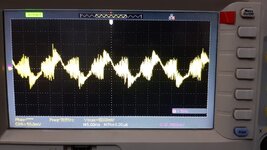
have attached the reading what i am getting between Triac gate and MT1 when the delay is 7.5ms
have attached 220V to 12V transfomer.
 

Attachments

  • Gate to MT1.jpeg
    Gate to MT1.jpeg
    130.9 KB · Views: 113

I have a small question.
As the triac does not go OFF until there is a current stored in it. Is there the possibility of opto triac MOC3021 which I am using also won't go OFF because of current across it. So I have to use snubber for opto triac also
 

remember the 3021 has a peak current of 1A, so a 330 ohm res needed to the gate of the main triac else you risk blowing the 3021 ( and the main triac ) when running on 230Vac

your picture above is no help as you don't show how the measurement was taken or the complete circuit. One can't even read the volts / div easily ...!

--- Updated ---

1651732120839.png

the snubber cap can be up to 100nF 375Vac rated. note the 360 ohm current limit.
 
Last edited:

remember the 3021 has a peak current of 1A, so a 330 ohm res needed to the gate of the main triac else you risk blowing the 3021 ( and the main triac ) when running on 230Vac

your picture above is no help as you don't show how the measurement was taken or the complete circuit. One can't even read the volts / div easily ...!

--- Updated ---

View attachment 176018
the snubber cap can be up to 100nF 375Vac rated. note the 360 ohm current limit.
Here the load is connected to T1 and as per my circuit the load is connected is T2.
Will also try changing the circuit
 

you really need to show " the WHOLE CIRCUIT " for readers to post any useful comments - else all is just guess work - we are not clairvoyant - nor do we have an all seeing crystal ball ....
 

Status
Not open for further replies.

Part and Inventory Search

Welcome to EDABoard.com

Sponsor

Back
Top