Continue to Site

Welcome to EDAboard.com

Welcome to our site! EDAboard.com is an international Electronics Discussion Forum focused on EDA software, circuits, schematics, books, theory, papers, asic, pld, 8051, DSP, Network, RF, Analog Design, PCB, Service Manuals... and a whole lot more! To participate you need to register. Registration is free. Click here to register now.

Phase Angle Control Using Controller

Status
Not open for further replies.

gauravkothari23

Advanced Member level 2
Joined
Mar 21, 2015
Messages
642
Helped
5
Reputation
10
Reaction score
4
Trophy points
1,298
Activity points
6,934
Hi all.
I am trying to Control the Speed of 120W AC Motor using controller NUC029LAN, Traic BT136, Zero Detection Circuit.
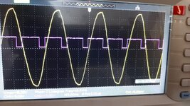
Have also attached the circuit diagram and some wave form. In the waveform i am triggering the Triac after 7ms delay after zero crossing is detected.
my problem is when incandescent bulb is connected as load, it works perfectly (wave form attached at 7ms of delay).
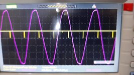
But when 120W AC motor is connected, i am not able to control the speed, it rotates at full speed only. (Wave form Attached at 7ms of Delay).
The waveform when motor is connected, is completely changed.
Have also attached the waveform of MCU Pin which is driving the Triac with reference of 12V AC, just for reference to confirm that there is no issue with the software part.
Can anybody please let me know where the issue is.
 

Attachments

  • Circuit Diagram.jpg
    Circuit Diagram.jpg
    121.2 KB · Views: 376
  • Motor-1.jpg
    Motor-1.jpg
    4.4 MB · Views: 223
  • Motor-2.jpg
    Motor-2.jpg
    4.8 MB · Views: 190
  • Motor-3.jpg
    Motor-3.jpg
    4.4 MB · Views: 233

That picture is as useful as a picture of your house You dont even say WHAT that board is.

You need to generate a trigger pulse of about 50uS. What don’t you understand about that?
yes, i understood that and that's actually what i am doing. at very first post i have also uploaded the waveform.
after zero cross voltage is detected, i switch the Triac ON (MUC PIN = 0) after 8 ms which works well. but when the delay time is less than 7.5ms of zero cross voltage, the motor rotates at full speed.
 

That is actually NOT what you’re doing, and your waveforms SHOW that you’re firing your trigger and leaving it on until the next zero cross.
 

Hi,

I agree with barry.
At least we have nothing that shows or proofs this.

I like to see pictures instead of text.
* a photo that shows the wiring. All scope connections, line, neutral, triac, ZCD circuit ... at least
* a scope picture. 3 channels: microcontroller_ZCD_signal, microcontroller_MOC_signal, load voltage

Klaus
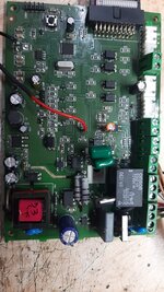
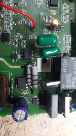
i have attached the PCB image.
--- Updated ---

the two green capacitors value 0.047uF are soldered in parallel in series with 100 ohms x 2 resistor for Triac snubber
--- Updated ---

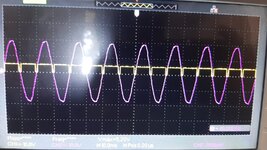
Zero Cross Circuit
--- Updated ---

MCU Pin
--- Updated ---

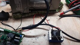
i have used this SCR module (Image attached) to test the motor, it works perfectly.
It is

AC 220V 2000W 8A SCR Motor Speed Controller Voltage.​


Attachments

  • WhatsApp Image 2022-05-02 at 11.20.47 AM.jpeg
    WhatsApp Image 2022-05-02 at 11.20.47 AM.jpeg
    222.8 KB · Views: 118
  • WhatsApp Image 2022-05-02 at 11.21.08 AM.jpeg
    WhatsApp Image 2022-05-02 at 11.21.08 AM.jpeg
    184.3 KB · Views: 119
  • WhatsApp Image 2022-05-02 at 11.21.34 AM.jpeg
    WhatsApp Image 2022-05-02 at 11.21.34 AM.jpeg
    184.5 KB · Views: 121
  • zero corss.jpeg
    zero corss.jpeg
    156 KB · Views: 124
  • MCU pin.jpeg
    MCU pin.jpeg
    155.5 KB · Views: 121
Last edited:

Hi,

The linked circuit does work in completely different situiation with RC delay and diac trigger. Not useuful to find the problem of your application. Stay focused on the problem.

* a photo that shows the wiring. All scope connections, line, neutral, triac, ZCD circuit ... at least
Which picture shows this? I see no scope connection at all. I see more wires than expected .. don´t know what they are used for.

* a scope picture. 3 channels: microcontroller_ZCD_signal, microcontroller_MOC_signal, load voltage
So I guess your scope is 2 channel only.
Both pictures show the sine to be about 12.7V RMS. How comes? I´d expect 230V?

Since "phase" = timing is important ... please choose the scope trigger at exactly "0V"

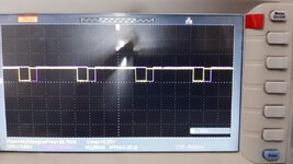
None of the pictures show the requested "short" trigger pulse in the range of 50...100us.

You say "7ms delay". Please tell us:
* which edge of the ZCD pulse is used as start of the delay
* .. to which edge of the trigger pulse

Just to be sure: in all pictures/photos/scope pictures/text .. we want to see the "in the faulty situation".
Properly working situations are likely not to show the cause of the problem.

Klaus
 

Hi,

The linked circuit does work in completely different situiation with RC delay and diac trigger. Not useuful to find the problem of your application. Stay focused on the problem.


Which picture shows this? I see no scope connection at all. I see more wires than expected .. don´t know what they are used for.


So I guess your scope is 2 channel only.
Both pictures show the sine to be about 12.7V RMS. How comes? I´d expect 230V?

Klaus
i have used 220 V to 12V trasfomer and transfomer output is being monitored on scope
--- Updated ---

Hi,

The linked circuit does work in completely different situiation with RC delay and diac trigger. Not useuful to find the problem of your application. Stay focused on the problem.


Which picture shows this? I see no scope connection at all. I see more wires than expected .. don´t know what they are used for.


So I guess your scope is 2 channel only.
Both pictures show the sine to be about 12.7V RMS. How comes? I´d expect 230V?

Since "phase" = timing is important ... please choose the scope trigger at exactly "0V"

None of the pictures show the requested "short" trigger pulse in the range of 50...100us.

You say "7ms delay". Please tell us:
* which edge of the ZCD pulse is used as start of the delay
* .. to which edge of the trigger pulse

Just to be sure: in all pictures/photos/scope pictures/text .. we want to see the "in the faulty situation".
Properly working situations are likely not to show the cause of the problem.

Klaus
this is the image for 50us trigger after 7.5ms where the motor rotates at full speed.
 

Attachments

  • 100us trigger.jpeg
    100us trigger.jpeg
    130.4 KB · Views: 128
Last edited:

Hi,

you know your application is a phase control .. this means timing critical.
A transformer will introduce some delay. Usually the smaller the more delay.
How much? We don´t know. But you need to know.
We even did not know it existed...

Don´t get me wrong. We need clear and complete informations we can rely on. Otherwise it takes long time until you get your circuit working.

Klaus
But without transfomer, how can i check the AC waveform. i cannot connect AC mains directly to scope probe.
what is the other way to check the AC waveform.
--- Updated ---

But without transfomer, how can i check the AC waveform. i cannot connect AC mains directly to scope probe.
what is the other way to check the AC waveform.
but cannot we take a reference from zero cross detection, are they more accurate then transfomer.
--- Updated ---

Hi,

you know your application is a phase control .. this means timing critical.
A transformer will introduce some delay. Usually the smaller the more delay.
How much? We don´t know. But you need to know.
We even did not know it existed...

Don´t get me wrong. We need clear and complete informations we can rely on. Otherwise it takes long time until you get your circuit working.

Klaus
the transfomer i am using is just for viewing purpose only,
actually i have used is zero detecting circuit as posted the circuit diagram in post 1
 
Last edited:

Hi,

But without transfomer, how can i check the AC waveform. i cannot connect AC mains directly to scope probe.
what is the other way to check the AC waveform.
A suitable scope probe...
A resistive divider ... introduces about zero delay.
A transformer which is specified for this usage. Regarding timing.
A reference ZCD circuit with specified timing.
It does not matter which one.... just one with known timing behaviour.

An isolating transformer from mains to your application increases safety and reduces GND problems.

but cannot we take a reference from zero cross detection, are they more accurate then transfomer.
Here is the exact problem.
The absolute reference to zero crossing timing is mains voltage. This is the one and only true reference.
For sure you may use ZCD output signal ... but only after knowing how the ZCD signal is related to the true zero cross reference.
You also may use the transformer --- but only after knowing how it is related to the true mains zero cross reference.

I´m interested in finding out what´s the root problem, then remove it.
Are you interested in the same?

Klaus
 

Hi,


A suitable scope probe...
A resistive divider ... introduces about zero delay.
A transformer which is specified for this usage. Regarding timing.
A reference ZCD circuit with specified timing.
It does not matter which one.... just one with known timing behaviour.

An isolating transformer from mains to your application increases safety and reduces GND problems.


Here is the exact problem.
The absolute reference to zero crossing timing is mains voltage. This is the one and only true reference.
For sure you may use ZCD output signal ... but only after knowing how the ZCD signal is related to the true zero cross reference.
You also may use the transformer --- but only after knowing how it is related to the true mains zero cross reference.

I´m interested in finding out what´s the root problem, then remove it.
Are you interested in the same?

Klaus
yes surely i am interested in finding out the root problem. please guide me.
--- Updated ---

Hi,


A suitable scope probe...
A resistive divider ... introduces about zero delay.
A transformer which is specified for this usage. Regarding timing.
A reference ZCD circuit with specified timing.
It does not matter which one.... just one with known timing behaviour.

An isolating transformer from mains to your application increases safety and reduces GND problems.


Here is the exact problem.
The absolute reference to zero crossing timing is mains voltage. This is the one and only true reference.
For sure you may use ZCD output signal ... but only after knowing how the ZCD signal is related to the true zero cross reference.
You also may use the transformer --- but only after knowing how it is related to the true mains zero cross reference.

I´m interested in finding out what´s the root problem, then remove it.
Are you interested in the same?

Klaus
here is my zero cross detection waveform on MCU interrupt pin (CH2) and MCU pin which is used to trigger the MOC3021 (CH1).
 

Attachments

  • Zero Cross & MCU Pin.jpeg
    Zero Cross & MCU Pin.jpeg
    131.8 KB · Views: 114
Last edited:

Hi,

So I don´t get the timing information from true mains to ZCD signal.

How to go on then? What´s your idea?


Klaus
 

do ZCD signals also create delay from true mains. how much it can be.
If so, sorry sir, but even i dont have any idea on how can we find out the delay timing.
--- Updated ---

Hi,

So I don´t get the timing information from true mains to ZCD signal.

How to go on then? What´s your idea?


Klaus
is there any other possibilites by changing the circuit. also dont know why it works well when triac is triggered after ZCD after around 8ms, but lower than that, it rotates at full speed
--- Updated ---

is the problem with snubber circuit...??
 
Last edited:

Hi,

also dont know why it works well when triac is triggered after ZCD after around 8ms, but lower than that, it rotates at full speed
I don´t know either, thus I tried to find out... I guess I failed.

Klaus
 

what trail and error we can do.
i have tried changing the timing at every interrupt.
for eg:
1st interrupt, timing would be 9ms, 2nd int = 7ms, 3rd int = 9ms, 4th = 7ms and so on. but it does not works, motor vibrates a lots

scondly what i have done is, i have made a count in interrupt, after every 4 counts of interrupt, i make the motor OFF for 2 counts and again ON for 4 Counts and OFF for 2 counts. but again motor vibrates a lot
 

SSR is terrible idea. It's already got a triac and triggering circuitry in it.

Now would be a good time to step back and maybe start over. First of all, your zero-crossing output looks wrong (Post #30). Why do you have the two signals laying on top of each other? Why do you not identify which signal is what?

I'm assuming you've got 50 Hz. Your "zero crossing" signal is low for quite a long time. And you are STILL generating a MUCH LONGER than 50uS trigger. Are you generating an interrupt on the falling edge of the zero-cross, or when the LEVEL is zero?

This is really not that complicated. Even if your zero-crossing detect signal has a large phase offset from the line, it's a fixed amount so all you have to do is just be aware of that offset and add (or subtract) that from the timing of your trigger.

Said another way, here's what I would do: When you detect a zero-cross, delay some amount, call it PHI, and then generate a 50uS pulse. All you have to do is change PHI and you should find some spot where the motor turns at some speed. The trigger will always occur at the same phase of the line and the speed should be constant, unless there's a problem with your software.

There are the other issues that have already be discussed here: excessive dv/dt, snubber, etc. Scope signals would be a BIG help. (especially right at the triac).
 

Now would be a good time to step back and maybe start over. First of all, your zero-crossing output looks wrong (Post #30). Why do you have the two signals laying on top of each other? Why do you not identify which signal is what?
CH2 is the MCU interrupt pin for Zero Cross Detection.
CH1 is MCU pin which is used to trigger the MOC3021.

As soon as the Interrupt is triggered, I switch OFF the motor (MCU PIN = 1), wait for some delay for approx 8ms, and then ON the motor again (MCU PIN = 0).
--- Updated ---

I'm assuming you've got 50 Hz. Your "zero crossing" signal is low for quite a long time. And you are STILL generating a MUCH LONGER than 50uS trigger. Are you generating an interrupt on the falling edge of the zero-cross, or when the LEVEL is zero?
Yes, I am generating an interrupt on falling edge. Interrupt is occurred as soon as the voltage level is below 2V
 
Last edited:

You are just not paying attention. I‘m done with this.

For the last time, because we keep telling you how to do this, and you keep ignoring us:

YOU DON’T TURN THE MOTOR OFF WITH THE TRIGGER.

The triac will turn off ONLY when the current through it equals zero.
 

Status
Not open for further replies.

Part and Inventory Search

Welcome to EDABoard.com

Sponsor

Back
Top