MAGLATRON
Member level 2

- Joined
- Sep 21, 2024
- Messages
- 52
- Helped
- 0
- Reputation
- 0
- Reaction score
- 2
- Trophy points
- 8
- Location
- England
- Activity points
- 195
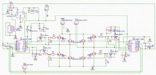
Hi there I've made this circuit that is supposed to take 8 supplies 10v each, and series 2 sets of 4 and then parallel those two sets and that voltage/current goes into the main inverter circuit my observations tell me that if I put 5v onto the VDD of the IR2110's and the signal voltage of 3.3 volts I can't get any wattage through r9- resistor right before the measureVoltshere tag; if I put the signals equal to the logic supply at 5v I get the power to spike in increments and want to know if this behaviour is correct if I put the logic supply 3.3 and the signal at 3.3 then the power spikes come back but a little less in magnitude. Is the power supposed to spike like that asc file need to remove .txt!! Am I even measuring the power in the correct place??


I don't understand the points system!!
 www.edaboard.com
Is there a way to emulate this waveform in LTSpice?
--- Updated ---
I don't understand the points system!!
--- Updated ---
[SOLVED] - Please Explain this Induced Voltage Waveform
Hello everyone. I'm inducing voltage into a coil using 4 magnets that are arranged circularly with alternating poles. You can see from the diagram that when the magnets are moved, EMF is induced into the coil. I was expecting to see a sine wave produced in the coil but the waveform shown is...
Attachments
Last edited:

