Continue to Site

Welcome to EDAboard.com

Welcome to our site! EDAboard.com is an international Electronics Discussion Forum focused on EDA software, circuits, schematics, books, theory, papers, asic, pld, 8051, DSP, Network, RF, Analog Design, PCB, Service Manuals... and a whole lot more! To participate you need to register. Registration is free. Click here to register now.

Hi, new here guys, not a total newb but need a bit of help IR2110 Inverter

MAGLATRON

Member level 2
Member level 2
Joined
Sep 21, 2024
Messages
52
Helped
0
Reputation
0
Reaction score
2
Trophy points
8
Location
England
Visit site
Activity points
195
Hi there I've made this circuit that is supposed to take 8 supplies 10v each, and series 2 sets of 4 and then parallel those two sets and that voltage/current goes into the main inverter circuit my observations tell me that if I put 5v onto the VDD of the IR2110's and the signal voltage of 3.3 volts I can't get any wattage through r9- resistor right before the measureVoltshere tag; if I put the signals equal to the logic supply at 5v I get the power to spike in increments and want to know if this behaviour is correct if I put the logic supply 3.3 and the signal at 3.3 then the power spikes come back but a little less in magnitude. Is the power supposed to spike like that asc file need to remove .txt!! Am I even measuring the power in the correct place??
1726938295264.png

1726938395230.png

--- Updated ---

I don't understand the points system!!
--- Updated ---

Is there a way to emulate this waveform in LTSpice?
 

Attachments

  • 40v 1.2amp - Copy.asc.txt
    9.6 KB · Views: 47
Last edited:
It's not perpetual motion and I don't know how to reduce file size of pics but I will find out today, all I really want is to do is work out how to rig up the inverter but I think I am just going to make the VDD 5volt and the HIN and LIN signals all 5volt because in the sim that seems to work! also going to get real life wave and put it in the form of PWL file and run the sim with that!
 
Guess you don't have an AC magnetic simulation that tells about available generator power. In ths case, it may be simpler to determine it empirically by loading either one coil or the rectified DC voltage (if you already built the circuit) with a variable load resistor. In your simulation, the average rectifier out is about 400 mA, I guess much above actually available power. Inverter power consumption is caused by unrealistic high motor current.
 
ok can you explain a little further because I don't understand any of that perhaps with a spice file? I've built the inverter if that's what you are asking not wired up the coils yet, what's the bit about the variable load? and how would it help? may sound stupid but how do you find the power by loading a coil?
Guess you don't have an AC magnetic simulation that tells about available generator power. In this case, it may be simpler to determine it empirically by loading either one coil or the rectified DC voltage (if you already built the circuit) with a variable load resistor. In your simulation, the average rectifier out is about 400 mA, I guess much above actually available power. Inverter power consumption is caused by unrealistic high motor current.
 
Last edited:
Welcome to the community! The IR2110 is a versatile high-voltage MOSFET and IGBT driver. What specific questions do you have about it? Are you looking for help with a particular application or need assistance with a specific circuit? Feel free to share more details about your project.
 
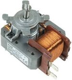
ok so there is an Arduino that provides the pulses at 50Hz with dead time of 2us I need to turn a fan oven motor that is 15watt so need to produce 20watt to cover losses, right now I am modelling the coils at 10v 128Hz with a substantial smoothing cap, but when I put it together I will reach a higher voltage! the transformer is 4:23 ratio, what I want to find out is the power that the four coils on either side in series and and then parallel the output of both sets so I repeat I want to find the power that they produce, the man FvM said I can confirm the result empirically but I don't understand the method of doing that, this is the motor I want to run hope I did the picture correct also want a suitable coil to represent the motor in spice. also my scope is an FNIRSI-1014D never used but going to try to get to grips with it!

so I asked chatgpt about the PWL and don't understand it, it goes on about defining a series of voltage points

"The FNIRSI 1014D comes with a built-in signal generator that supports various waveform outputs, including the PWL (Piecewise Linear) function. This function can be used to generate custom waveforms by defining a series of voltage points over time, allowing more complex signal outputs."

do you know how to record waveforms to make PWL files please?

I found this tutorial


Attachments

  • motor.jpg
    motor.jpg
    6.9 KB · Views: 34
Last edited:
I think this is the 1st LEGO Motor-Generator I've ever seen.

You may view power in any LTspice component with ^+ mouse click to see new thermal icon and plot then modify equation to get efficiency something like = "V1drop*Iin /V2drop*Iout" Generator or stored reactive power = -ve Pd, Load = +Pd

Shaded pole motors might not be high Eff., while max power transfer is at 50% effic.
do you like the LEGO?
so my coils in spice are making 11watt rms which I think is good to be fair I don't know what drop in or out means or generator or stored reactive power means either could you perhaps give me a recap please

so do you recommend a motor that spins at similar speed 3200 RPM and same wattage 15watt @ 230v?

and BTW it is actually alt + left click for power
 
Last edited:
You should submit IP design to LEGO for a prize!

correction : Power Plot is ALT+ not ^=Ctrl-click

Voltage drop is the difference between two nodes e.g. V(N001-N005)

e.g. for FET the Rs of gate and Drains with capacitance causes power dissipation.
V(N001,N005)*Id(M1)+V(N003,N005)*Ig(M1)

Here is a random design of a half-bridge driving an LC load
Note the polarity of power for L shows negative Watts for stored reactive power ( or energy per cycle) while R is +ve Pd.

1727196344928.png


I'm still trying to figure out how to organize my libraries and include references to IRF devices in LT software. (*&^%&^$%@#) while suffering from jet-lag after 2 weeks on the other side of the planet.

1727198486627.png
 
sorry for ignorance, I don't get it here's my circuit perhaps you could shed some light on the workings of it
I think I get it a bit the blue is real voltage?
and plus I still don't get where you use the Ctrl + left click
can you explain in a bit more detail please Mr D.A.
--- Updated ---

You should submit IP design to LEGO for a prize!

correction : Power Plot is ALT+ not ^=Ctrl-click

Voltage drop is the difference between two nodes e.g. V(N001-N005)

e.g. for FET the Rs of gate and Drains with capacitance causes power dissipation.
V(N001,N005)*Id(M1)+V(N003,N005)*Ig(M1)

Here is a random design of a half-bridge driving an LC load
Note the polarity of power for L shows negative Watts for stored reactive power ( or energy per cycle) while R is +ve Pd.

View attachment 194122


I'm still trying to figure out how to organize my libraries and include references to IRF devices in LT software. (*&^%&^$%@#) while suffering from jet-lag after 2 weeks on the other side of the planet.

View attachment 194123
I don't understand the graph can you explain another way please
 

Attachments

  • 40v.asc.txt
    9.1 KB · Views: 25
Last edited:
so I've calculated the inductance by this equation L = Z/2pi*f
f is 50Hz
Z is impedance and the resistance is roughly 15% less than impedance so my coils have resistance of 2.5ohm and the inductance for it is 9.36mH
I'm using a step up transformer
so the primary resistance is 0.1ohm and the inductance works out to be 0.376mH
secondary resistance 3ohm inductance 11.24mH
I want to add the inductance to the 10volt ac supplies
also put the values for the transformer in and the resistances for the 10volt ac supplies and the output is not of the desired
now, I took the square root of both the 11.24 and 0.376 corresponding answers 3.3526 and 0.613 and that ratio is near enough 4 : 23 which is correct my transformer is 40 : 230
not sure what I am doing wrong
1727257175518.png
 

Attachments

  • 40v - Copy.asc.txt
    9.4 KB · Views: 23
Last edited:
anyway on the practical side I'm in the process of putting the cores in the coils they're made from ferrite welding rods with the flux crumbled off done two 6 more to go!
 
how do you find the power by loading a coil?
I started by watching my oscilloscope hooked up to the coil. I held a neodymium magnet between my fingers, and moved it quickly past the coil. Experimenting, I saw a variety of waveforms.

I hooked up two led's to the coil, one pointing in one direction, the other pointing the opposite direction. Again moving the magnet close to the coil, I got slight voltage and slight current. I'm not sure it even lit either led dimly.

You should get better results. The power you get out is a combination of factors: number of turns in the coil, strength of the magnet, speed it passes the coil, how close it gets to the coil.
 
LTspice can probe voltage or amps by mouse position after a run and the pointer changes icon or watts (+ alt key) changes to a thermometer icon. So you can delete R9 input current sensor which has an invalid integer value of 1r. Then prove current with the arrow icon when pointing at the correct location (your find them).

Plots can be moved, added, deleted as well as traces in each plot then edited. Using lots of tag names replaces the otherwise confusing node #s in plots for easier understanding.

Regarding filtering ripple, you know how to compute X(f) reactance and load ratios so you want a low impedance source to step up voltage and adding primary L will reduce your step up ratio, but adding equal amounts of powdered core will raise both Lp, Ls . The motor impedance is inductive with no work and parallel resistive with torque I believe just like a generator while BEMF voltage is RPM dependant in V/RPM for no load.

A strong motor will have more torque and thus there is a series DCR, series L and a parallel load R in the model. Inertial mass viscosity and other parameters cannot be added easily to LTspice without knowing the formulae (don’t ask) Magnetic coupling and reducing the air gap after the k coupling factor like in a transformer and thus lower impedance and more current at low RPM.

Getting back to the DCDC bridge regulator also has impedance on input and output so a soft start on the Vref helps it get start while the motor ramps up.
These are all handwaving generalizations, which I hope are correct until you have some definitive specs for V, I, P, ripple, RPM, torque, load
 
putting the cores in the coils they're made from ferrite welding rods with the flux crumbled off done two 6 more to go!
Your home-brew method is ingenious although I wonder if it helps to put ferrite close to the magnets. I started to make a brushless motor by winding a coil with wire wrapped around a steel nail. Then I realized steel would attract the magnets. Won't the magnets want to stop directly over the coils? Rather than continue I decided to put off the project until I gain adequate knowledge. Possibly ferrite (soft iron) is a more suitable material for the core.

Notice however that graphics of an electrical generator show wires moving though a magnetic field without a core? The core's purpose is to attract and concentrate flux. A ferrous coil assists energy storage. However I'm not sure of the effect in your DC (or is it AC) generator.
 
so I done half on my coils with the welding rods! the magnetic cogging is too much for the drone motor to get going - and to handle! so have to have a re-think, the idea is that with a heavy flywheel, the momentum of it will take the magnets past the cores with ease, just need to get it going. The rubber wheel method is no good because the motor just spins and does not tract with the rubber flywheel, so now I am thinking to use sprocket and chain. I have to wait till payday to get some new parts! going to use a PWM motor speed controller and also use a motor that I salvaged from a remote control car 30watt 12v getting a mini-moto sprockets and chain, 300mm * 9.5mm rod for the axle. and build from there! take a couple of weeks the get money and buy and then put together, if you guys have questions feel free but if not I'm not going to post for a while unless I come up with something in the meantime!
 
Last edited:
yup :) thanks for that D.A. it feels as though when the "lumpiness" or "cogging" is ironed out when flywheel effect takes over, because the law of inertia, things tend to want to stay at the same speed, so then it won't take too much to keep it at a steady speed.
 
Last edited:
As soon as you start drawing electrical power from a generator, it starts to resist being turned. Picture one of those hand-crank emergency flashlights which need us to supply arm-power in order to keep a few led's lit. Even that type is not so easy to turn.

To draw 20W requires proportionally more effort. You have a mechanical device which spins your generator (magnets). As soon as your system draws current through the coils, they'll oppose the magnets passing close. Your spinning mechanism will not want to spin. It will take surprising effort (I'm not sure how much effort) just to keep your armature rotating at operating speed.
 

LaTeX Commands Quick-Menu:

Similar threads

Part and Inventory Search

Welcome to EDABoard.com

Sponsor

Back
Top