Continue to Site

Welcome to EDAboard.com

Welcome to our site! EDAboard.com is an international Electronics Discussion Forum focused on EDA software, circuits, schematics, books, theory, papers, asic, pld, 8051, DSP, Network, RF, Analog Design, PCB, Service Manuals... and a whole lot more! To participate you need to register. Registration is free. Click here to register now.

Help re-creating a replica movie prop

Status
Not open for further replies.
If you are using a small battery as the power source I wouldn't worry, the only vulnerable parts are the 555s and they are pretty tough guys. I doubt a small battery could produce enough to kill them.

edit- lift the bottom off the protoboard and you will see what I mean about the connections.

Brian.
 

I'm super confused by this.I added a jumper from the power bus to the battery and heard a low, quick tone, but I can't replicate it. Also, I think my wires are still a mess.

I think the entire problem is from toggle switch to Pin 2 of the fist 555.

- - - Updated - - -

I think I got it, but The volume is very low. What would I change to increase volume?? Also, it's working but without the diode in the circuit at all. And I had to put the small black capacitor (after all the diodes) to ground, which I don't have on my circuit drawing. Do I have to connect that to ground on my drawing???

This is so confusing.
 

The schematic in post #99 is the one to follow.

I'm puzzled by the small black capacitor, the one going to the switch should be a 10nF non polarized type but it looks like an electrolytic, have you confused it with the one on pins 1 and 2?

The volume is almost entirely controlled by the resistor in series with the loudspeaker, the one in the photographs is 10K (brown, black, orange) but it should be 100 Ohms (brown, black, brown). The higher the value the less current can flow to the loudspeaker so the volume would be lower.

Brian.
 

Ok! Looks like it's work, and it's loud. Duration is perfect, I'll hook up the potentiometer later to adjust pitch. How do I control volume? Possibly lower...

I only did this test with one toggle, not all twelve. Everything seems great, but:

1)No Diode is used. When it is, I get a constant tone. Do I still need them in my design?

2) The capacitor just after the toggles, before pin 2 of the first 555, needs to be grounded. In my circuit board design it's just floating. I guess I have to update that? Brian, this is the capacitor you referred to just above this post.

3) When I throw the toggle to OFF I can hear it through the speaker. Can this be corrected with what Forrest Mimms refers to as a bounce-free design?

By the way, no more dimming or wonky numbers occurring on the 7 segments.

Here's a video of me cupping the speaker for the video my fiance shot: https://youtu.be/2w6I6543KFU
 
Last edited:

Hi John,

Just seen how things are progressing, you'll have an engineering degree by year end at this rate ;). It's exciting, isn't it, once things start working and falling into place? Glad for you, electronics is wonderful fun and great to learn how things work and can be used.

Glad it's working. You need to breadboard the whole design, otherwise it's taking an unnecessarily "unscientific" (and sloppy) risk and therefore, beware unwelcome surprises later.

Is there a power and a ground connection on the breadboard? I just ask as I couldn't really see it, the brown cable is power and yellow is ground, I think.

1a) Follow the schematic provided.

1b) The diodes are all necessary.

2) Lord knows what that capacitor is but it shouldn't be there and is not at all needed to make that circuit work; I've made plenty of timer triggered by longer than acceptable pulse using a 100pF capacitor in series to know you're doing something weird, no grounded and no floating capacitor should be anywhere on that board... And I'd hazard a guess that if it works like that you may be doing something else weird elsewhere on the breadboard, maybe.

3) Not sure, use a debounce circuit anyway, always good practice.

4a) Honestly, I recommend taking the circuit apart, starting from scratch and putting the two timers on one breadboard, following the actual schematic, not inventing things that aren't on the schematic to make it "work", and especially using red for power, black for ground, whatever colour for inputs, whatever color for outputs - whatever is anything but red or black. Short flat, neat cables help see what one is doing, as are trimmed resistors that lie flush with the board - where possible.

4b) Vast experience of bungle-learning my way through electronics by mostly breadboarding and studying, I would say that at first the breadboard is a rather confusing place, all new things I didn't read more than the pinout about and components I didn't care to understand much and loads of wires and re-checking datasheets for pin numbers when things weren't working and and even then still getting some of them wrong sometimes and connecting things backwards and wires not being in the right holes but seeming so the first time I looked and forgetting to put either a power or a ground cable somewhere and not seeing until an hour later of botching invented solutions that don't work on a correct circuit tells me that once lost in there, any wrong way out looks like the exit and a relief but may not be the right approach. And I thought I knew what I was doing. ...And I still make a lot of mistakes so I'm not being preachy.

4c) I'd really start that again and put a power cable and a ground cable in the breadboard power strip, for starters, but that's just me being finickety.

4d) Follow the schematic provided calmly and meticulously and re-check progress in small stages.

If you really have it working as needed on the final board that'll be made, great, one less thing to do and good for you!

- - - Updated - - -

...Nice video... Not familiar with that song (joke). Good stuff!
 
Well done!

The only way to adjust the volume is by increasing the resistor value in series with the loudspeaker. As it is too loud, you need to increase the resistance. Do not let the value go below about 100 Ohms or you will run into the 555 overload scenario again. The best solution is to keep the existing resistor and add a variable resistance in series with it, I would think 1K would be a suitable value.

You still need the diodes, if you leave them out it would imply all the switches were wired in parallel so you would lose the ability to select individual digits with the switch. The wiring should be:
wire to switch ----- diode (banded end) + resistor to supply + 10nF capacitor
other end of 10nF capacitor + resistor to supply + pin 2 of the first 555.

The schematic in post #99 is correct but the IC shown is a 556, not a 555 so use the pin names rather than numbers. The 555 has 8 pins, the 556 has 14 pins, it has two 555s in a single package but they share the same supply and ground pins.

If I explain how it works it might help you understand:
A capacitor stores charge, it is like a battery in that respect but it doesn't generate electricity, it can only release as much as you have put into it. With the resistor to supply at both ends of the capacitor, it has the same voltage on both pins so it doesn't store any charge. When the switch closes, the end nearest the switch has a conduction path to ground via the diode and switch so the capacitor starts to charge up. As it draws current to charge up, the voltage at the 555 end of the capacitor drops because the current has to flow through the 10K resistor so you get a downward spike at that instant. As the capacitor reaches full charge, the current drops to zero and the voltage at the 555 trigger input returns to supply level. When the switch is opened, the capacitor discharges through the 10K and 100K resistor until it has nothing across it again. The timer (monostable) in the 555 is triggered by a downward spike on it's trigger, it starts a fixed time delay which is what sets the duration of the beep.

The diodes are needed to isolate the switches from each other. The spike should be generated when any of the switches close but the other function of the switch should not interact with the other switches.

Debounce isn't needed at all, the monostable will not retrigger until it's time is up.

Brian.
 
Thank you! If you recall, you recommended 50k potentiometers. One for duration (now not needed) and the other to go on pin 5 of the second 555 to adjust pitch (see post 110). Does this mean the capacitor from pin 5 of chip 2 is removed??

I'm actually referencing and using the 555 schematic D123 provided. I hope that's ok, it what I based my circuit on, too.

Still confused as to the order of the diodes, I'll re-read your post. However, the breadboard confuses me. BUT, I've already designed the circuit and both you and D reviewed. So, I assume the circuit is good and ready for production. Please see the picture in post 122 with D123s additions.

Still, what do I do about the capacitor to ground? Was I wrong to buy and use that leading up to pin 2 of chip 1? Is there a different type I should buy to replace it?
 
Last edited:

Hi

:)... What value is that capacitor? Electrolytics are too big to use there, the smallest I have seen is a 1uF non-polarised one; 100pF works fine for the purpose it's needed for. It should be horizontal between two vertical resistors that both go to V+ at one end. The "left" side of the capacitor and botttom of the "left" resistor meet where all the diodes join together; the "right" side of that capacitor shoudl meet the bottom of the "right" resistor and pin 2 of the timer/555.
 

Thanks for the encouraging words and support, D. I'm having a blast learning electronics.

It's a 10uF. Seems I bought the right value, but wrong type.

You looked over and added to my circuit. It's correct, right? Not the breadboard, the actual trace circuit from a few days ago.
I think it is, because I followed that today to put the breadboard together, but I referenced your schematic for parts, which was super helpful : ). I think I'm good to go. Just have figure out the diodes and this one rogue capacitor.
 
Last edited:

Hi John,

Not sure if you do actually mean the first capacitor from the left in the schematic in post #99... If you do, 10uF is enormous; it should be 0.01uF (10nF) or 0.00001uF (100pF).

To the best of my knowledge, the corrected version of the pcb is correct.

The stripe on your diode faces the switches. Here the cathodes (stripy ends) point to ground and connect to your switches and the anodes (not stripy ends) are connected together and point to the positive supply via the resistor and capacitor going into the 555. If it helps, cathode indicates the conventional flow of the power supply - in your circuit V+ is high until a switch closes and then voltage flows through the anode end into the cathode and out of the diode through the switch to ground.

The arrow on the diode symbol shows which way things will flow, the perpendicular line across the arrow shows where it blocks flow. They are there to separate switch signals. When you close a switch there is a path to ground through one of them.
 
i actually have the .01uF capacitors, too. But, when I remove the wrong one, and put the right one from the resistor going to power and pin 2 of the 555, I'm back to a loud click fro
m the speaker, no tone. I'm really confused by the 555 circuit.
 
Last edited:

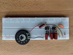
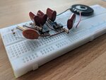
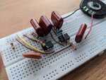
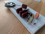
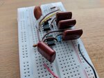
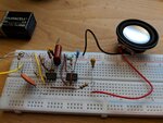
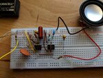
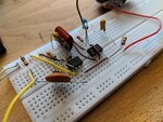
I neatly repopulated the bread board, but it's still not working. I took photos below if you guys are up for examining them
No power/toggle hooked up for photos. Does toggle go into the power bus?? So confusing.

MVIMG_20181224_131415.jpgMVIMG_20181224_131421.jpgMVIMG_20181224_131425.jpgMVIMG_20181224_131430.jpgMVIMG_20181224_131436.jpg
 

Hi,

Toggle switches connect to ground. From the pictures I'm afraid to say there a lot of incorrect wiring things going on in there, John, probably the reason for the crackle.

You're shorting the output of pin 3 on timer 2/The resistor goes out of and back into pin 3 the way you have put it. The resistor out of pin 3 on timer 2 goes into a different row on the breadboard and the capacitor and speaker positives go into the same row as that; the other ends/negative ends of the capacitor and speaker go to the ground rail.

You've got one end of that capacitor in the reset pin "column", it shouldn't be there.

There's a 0.1uF (100nF) capacitor missing from pin 5 on timer 2, that goes from pin 5 to the ground rail.

Remember that on a breadboard the strips 5 holes long (let's call them columns) all communicate with each other, the ones perpendicular to those (let's call them rows) don't communicate with each other.

Don't bend resistor leads so close to the resistor body, dude, that's criminally negligent, and have a heart, resistors have feeling too ;). Rather than do that, it's bad for the resistors, bend them around 5 mm from the ceramic body, at least. Make the resistors vertical if they don't fit horizontally. Make one lead about 1cm long and the other about 2cm long. Don't bend the 1cm lead but do bend the 2cm one to make an arch downwards so it is in line with the un-bent pin (a U shape).

- - - Updated - - -

...Call me fussy and someone who uses "unnecessary" components but a) every document tells you to decouple ICs with x amount of capacitance and b) I never put an IC anywhere that isn't decoupled from the supply with at least 0.1uF to a preferable 1.2uF across its V+ and V- pins. Timer 2 on your board is turning on and off frequently when it's powering the speaker so it will be drawing current at different rates during this on/off switching activity to supply power to the speaker and capacitor and therefore a little reservoir of power across its supply pins is helpful, both to the timer and to anything else in the vicinity on your complete circuit.
 
Still wrong I'm afraid.

Look closely:
You have a capacitor to the red wire from the loudspeaker that shouldn't be there, it should be a 100 Ohm resistor.
The loudspeaker is fed from pin 4 when it should be pin 3.
As shown clearly in the 3rd picture, there is a shorted out 47K resistor on pin 3 of the rightmost 555.

I'll build a copy here and photograph it for you shortly.

Brian.

[Edit 30 minutes later: using the exact circuit I originally gave with d123's input capacitor added, it works perfectly. It is almost 10pm on Christmas Eve so forgive me for not making a video at the moment! I'll try to make one tomorrow for you. What city or time zone are you in?]
 

D and Brian,

Thank you for checking and correcting. I'm an idiot with these breadboards. I can design a circuit, but I can't follow a breadboard!

Brian, please spend this time with family and friends. You can send a video after the holiday. I live in NYC, and I'm about to start frying up all the seafood for our Christmas Eve meal! Merry Christmas to you and everyone in this thread that's celebrating.
 

I hope everyone had a happy new year!

I realized I had quite a few components of the wrong value, so I purchased what was needed. Now, all components in these photos match the schematic in post 99, but still no sound. I even went from an 8 ohm speaker to a 4 ohm.

Brian-

Any chance of posting those detailed photos or video? I'm just about ready to quit on the beep circuit. I really can't figure this out and now I'm wasting money on parts.

Thanks!
John

MVIMG_20190102_181834.jpgMVIMG_20190102_181837.jpgMVIMG_20190102_181845.jpg
 

Hi,

Happy New Year to you, too!

The first timer has a resistor fromthe reset pin that goes to V+, that should only be a wire to V+. The resistor from pin2 should be a 10k one.

The second timer is missing an 100nF (0.1uF) capacitor from pin 5 to ground. The resistor to the speaker is huge, it's supposed to be 100 Ohms.

Follow the component values in the schematic, you keep changing things (?!).
 

This is my version to prove it works, I built it on a smaller version of board than yours:
20190103_091247a.jpg
This shows what is inside your proto board:
20190103_091336a.jpg
And this is a close up (sorry, no macro lens!) of one of the small contact strips inside your proto board:
20190103_091653a.jpg

You can see why it is wrong to fit both ends of a component to the same row of holes, they are all linked on the same spring contact underneath.
You will note that the long strips on the board edges link all the contacts together, these are the ones with the blue and red lines on the top side. On mine there was a break half way along on all of them so I had to open it up and solder the halves together. Also note that on the first picture, I linked the blue on one side to the blue on the other and the same linking red to red. This gave me a negative and positive supply on both edges of the board to make construction easier. From an electrical point of view, they are the same connection but it saves crossing all the component legs over to one side. The one I built here works exactly as designed and momentarily touching the flying black wire to the end of the diode triggers a single beep from the loudspeaker.

Brian.
 

Hi,

Just put this together, I hope between both Brian's and my breadboard examples you can get it going properly. Make sure you're not using run-down batteries, testing is probably less irritating with a "wall-wart" power supply (and they're cheap, the ones that can be adjusted from 5V, 6V, 9V to 12V with 1A output power).

timer speaker circuit.jpg
 

That big 10uF capacitor across the loudspeaker serves no useful purpose, it can be removed quite safely.

Brian.
 

Status
Not open for further replies.

Part and Inventory Search

Welcome to EDABoard.com

Sponsor

Back
Top