Continue to Site

Welcome to EDAboard.com

Welcome to our site! EDAboard.com is an international Electronics Discussion Forum focused on EDA software, circuits, schematics, books, theory, papers, asic, pld, 8051, DSP, Network, RF, Analog Design, PCB, Service Manuals... and a whole lot more! To participate you need to register. Registration is free. Click here to register now.

Help re-creating a replica movie prop

Status
Not open for further replies.
Hi guys,

I just followed both of your photos to the T, and nothing. D, I haven't changed any components, if anything, I replaced some with the right values. I also noticed you added capacitors to both pin 8s and the first pin 4 that I don't see on your schematics, my trace diagram, or Brain's breadboard. So, this continues to confuse me, and I don't know if my trace diagram is correct anymore. I see some capacitors going to ground that on my diagram are not. though I think you said the diagram looked good. But to me, it differs than your breadboards. So, I'm confused.

No sound whatsoever, I'm about to smash this circuit against my bench.
 
Last edited:

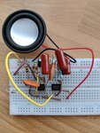
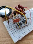
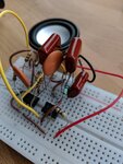
Before trashing the bench - double check the resistor in series with the loudspeaker. The photographs shows 100K but it should be 100 Ohms, that would reduce the volume by 1,000 times and make it inaudible.

Brian.
 
Hi John,

Welcome to the wonderful world of electronics. It's like debating logic with strong-willed cats sometimes, frustrating but you get there in the end.

The resistor from pin 3 on timer 2 to the speaker looks like a 100 kiloOhm one to me, not 100 Ohms, big difference and it won't make any sound with a large resistor. And I'm suspicious about that huge polyester capacitor (red wine coloured one), I have 10uF, 100V that size; the 100nF, 250V are 1/10th that size. I doubt that is a 100nF capacitor on your circuit, unless it has a 10 zillion Volt rating ;).

Do you have a multimeter (DMM) or an oscilloscope? You need to start measuring voltages at the respective output pins to see what happens when a switch is clicked. Then repeat flicking a switch and measure what happens at pin 2 of the first timer. If not, but you do have some LEDs, you could put one LED on the output of each timer (as well as what's meant to be there) - in parallel, not series, to the actual loads - and see what lights up when you flick a switch. If they both light up, which they should, change the second timer's 100nF capacitor (from pins 2 and 6) for a 10uF to see if the LED flashes or not.

The two 100nF that are on the breadboard from V+ and ground to pin 8 and pin 1 of each timer are for decoupling. The circuit will work without them but it's good practice to include them.

I'm sure you are, but do take care to use the right value capacitor in its place.

Are you separating the other end of the diodes? They need to be in separate columns (the ones that are 5 holes long) on the breadboard.

How about trying with a different speaker? Do you have some old landline phone or something similar you can pull apart to scavenge one?

Maybe it's something to do with the battery, unlikely unless they're wornout, but still. Those batteries are all but useless when the voltage falls to around 7V, if you can measure them with a DMM. Try with a power supply, it can work from 5V up to 15V, so even the adapter from an old router or phone charger will be fine. Read the voltage and current rating on some "wall-wart" you may have lying around, they're usually 5V or 12V and from 0.5A to 1A. If you can't check the polarity of the wires, use a sacrificial LED and resistor to check which wire is + (5V/9V/12V) and which is - (0V) before frying your circuit with a reverse polarity accident.

What sort of 555s are you using? What is the prefix: LM/LMC/TLC/NE/SE/SA? Not all 555 cicuits will work with different models/versions, but most do. I've done this circuit with LMC555s (CMOS) and SE555s (TTL) and both versions work.
 
Hi Brian,

The lowest I have is a 470 ohm, and it didn't do anything.

Hi D,

I'm using NE555P IC 555 Texas Instruments. I just bought a Multimeter last week. The red capacitors say 200V. I don't have Diodes in place because I still don't see how to add the switch to the breadboard. For me, it isn't clearly illustrated in Brian's photos (I'm sure it is, but I don't understand), and in yours, the left side of the frame is unfortunately cropped. I'm only testing this with one switch, if that helps. Fresh 9v installed this morning.

So far, I've only been able to achieve the tone when I accidentally assembled the circuit in my youtube video, but since it was suggested that I was wrong in doing that, I disassembled, and cannot remember how I did it.
 

I would add that this is a two part circuit - part one produces the length of pulse that makes part two produce the tone. The usual strategy when something doesn't work is to divide the problem into sections and in this case it is very easy to do. If the resistor doesn't do the trick, try this:

1. remove the link between pin 3 of the first 555 and pin 4 of the second 555.
2. connect pin 4 of the second 555 to the positive supply.

It will stop the trigger circuit operating and instead make the second part produce a continuous tone. You need to get the tone part working before worrying about anything else. When you hear the tone, put the circuit back as it was and we can start investigating why the duration pulse isn't being produced.

I know how frustrating this can be, believe me, I've been in this game for more years that I care to think of and I still get stuck in loop looking for something right under my eyes sometimes.

Brian.
 
Hi guys,

I found that walking away from it for a few days helped. This morning I tore it down and rebuilt on the breadboard, using D's photo as a guide (but excluded the capacitor before the speaker). I then tried Brian's suggestion of bypassing chip 1, and I indeed got a continuous tone from the speaker.

But, for the life of me, I cannot figure out how to connect the toggle switch to this. Whenever I try, I get radio silence. I think, I don't know, but I think this is why I can't get the circuit to work with the toggle. At this point, I don't believe anything on chip 1 is wired incorrectly. If one of you can post a clear photo of how the switch comes into the breadboard and into chip 1, as well as how all other power and ground from the battery come into the breadboard, I'd really appreciate it.

Brian, friendly reminder that I have (2) 50k Potentiometers to tap into the the circuit with to control pitch and duration, but we can cross that bridge after the circuit works. I think I know how to add those on my own...

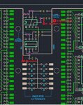
Lastly, can you both re-review the attached image? I think it was initially agreed on that this circuit was correct, but now I think it's missing the capacitor from pin 4 of chip 1 that is indeed in D's photo and now on my breadboard. Once my breadboard works, I have to make sure this circuit diagram works before adding it to the large board in the briefcase.

D, you added the red edits.
John movie prop replica PCB.jpg


Thanks!
John
 

You can simply connect pin 4 to the + supply, the reason d123 added it was to prevent a spurious single beep when the power is first turned on. On my prototype it didn't beep anyway but in theory it could happen. If you don't mind the risk of one extra beep, leave it connected to '+' and leave R1/C1 out altogether.

There is an error on the PCB at pin 2 of the first 555. The resistors and capacitor are wrong, there should be a resistor from pin 2 to + and a capacitor where you have the purple 'R'. I've drawn the part of the schematic below for you:
20190105_164916a.jpg
Sorry for the poor quality!

The trigger signal is created by grounding any of the cathode ends of the diodes. The switches already have ground on one side of them so all you do is link from each diode to the 'non-grounded' pin on each of the switches. The idea of using a monostable timer is that no matter how short or long the trigger pulse is, it produces one output pulse of known length. On my prototype all I did was touch the flying black wire to the end of the diode. The idea is that as any of the switches close (to update your digits) it also connects the end of a diode to ground and that produces a brief pulse to trigger the monostable. Even if you hold the switch closed it will not continue to beep but if you release the switch it re-primes the timer ready for another trigger.

When you connected the enable on the second 555 to + and got the tone it proved the astable circuit was working, putting the high voltage on enable did just that, it enabled the oscillator. When linked to the first 555 it does exactly the same but the high is produced by the monostable and only for the length of the beep.

Brian.
 
Thanks, Brian. Very helpful. Sorry, I'm going to need a photo or drawing of the switch to breadboard/Diode.

Does power and ground from battery also go into the strips on the breadboard? Or is power only supplied from the switch to the diodes?
 

You still need the power and ground to the beep circuit all the time, the switch only works as a trigger to start the beep.
Luckily, I haven't had time to dismantle the protoboard yet but I'm afraid I don't have any switches to hand at the moment so you will have to imagine one at the ends of the black and orange wires. The black wire is the ground which should go all around the circuitry, the orange wire is the one that goes to the 'not grounded' side of the toggle switch. I have only one diode on the board but you would have 12 of them with their anode ends all joined together and a wire from each cathode to one of the 12 toggle switches. Think of it as 12 diodes and orange wires instead of one.

20190105_172612a.jpg

I have to leave shortly so I may not be able to reply for a few hours.

Brian.
 

Ok, So I think I'm close. I got the toggle wired, but I get a long, low pitch beep that last for 5 seconds. I assume I can adjust that by adding the potentiometers?

Also, no matter what poles I put the wires on, the toggle only works when it starts from an outside pole (angled position) and click into the center (vertical) position. However, my digits, and the movie prop, function when the switch starts in the center position (vertical) and travels to an angled position.

So, I must have something crossed??
 

Ok, So I think I'm close. I got the toggle wired, but I get a long, low pitch beep that last for 5 seconds. I assume I can adjust that by adding the potentiometers?

TIMER 2: You can, but use a much smaller resistor with the trimpot(s). If it's making a low noise, then the resistor(s) need to be smaller/lower value. Or, try with a smaller capacitor on timer 2 (where pins 2 and 6 meet it an the second resistor), two 100nF in series halve the capacitance to 50nF, or two 10nF in parallel double the capacitance to 20nF. The smaller the capacitor, the faster it oscillates and the higher the pitch.

TIMER 1: If you want the beep to last for less time, maybe one second (and if you're using a 10uF on timer 1 at present), try 2.2uF (or 2 x 1uF in parallel), or put two 10uF in series for 5uF (presumably about 2.5 seconds duration/controlling timer 2).

Also, no matter what poles I put the wires on, the toggle only works when it starts from an outside pole (angled position) and click into the center (vertical) position. However, my digits, and the movie prop, function when the switch starts in the center position (vertical) and travels to an angled position.

So, I must have something crossed??

John, give a link to the datasheet or the exact product name for the switch, please. You say swapping wires over on the toggle switch pins/terminals doesn't change anything? You could, if you fancy trying, use the continuity tester on one of the toggle switches to see which way round you'd need to wire it for it to do what you need.
 
My beep only lasts about half a second so I would suspect you have a resistor or capacitor around 10 times bigger in value than it should be.
Can you post a photograph so we can see the values on the components please.

Brian.
 

Hi guys,

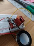
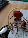
Photos attached. As for the switch, it's the same switch being used to turn the digits on and off and works fine there. Centered is off, down (angled) on.

But it works in the reverse for the beep circuit. Weird.

The large brown capacitors are .1uF, which according to a conversion chart I found is comparable to the 100nF required for this circuit. Is that ok?

MVIMG_20190105_152732.jpg
MVIMG_20190105_152800.jpg
MVIMG_20190105_152810.jpg
MVIMG_20190105_152904.jpg
MVIMG_20190105_152950.jpg
 

Looks OK to me so I'm not sure why the strange timings. Sorry but time is late here and I still have work to do so I'll have to respond further tomorrow. Time zones are a pain aren't they!

Brian.
 

Hi,

I think the first 100k (that has a lead that connects to the 10nF ceramic capacitor) has a lead in the ground rail and it needs to be in the positive supply rail.

There's a 10k on the second timer that goes to pin 7 that I can't see whether it's connected to positive supply or ground, I guess it is on the positive supply line.

Yes, the 100nF are fine/the right value.

Regarding the switch, if moving that 100k resistor lead doesn't solve the toggle position issue, we can think of it this way. When the first timer should be off, the switches are all in the centre position, so the internal switch contacts do not touch each other and that is an OPEN connection, due to this pin2 on the first timer only sees the positive rail; when you move the switch lever, the internal switch contacts touch and it is now CLOSED, creating a path to ground, now the positive supply voltage goes to ground rather than to pin 2 so pin 2 sees 0V and triggers the timer to run an x seconds long pulse.

With the other part of your circuit, it's just doing the opposite: open = off, closed = path to positive supply. Switches are like drawbridges, maybe. It's important to differentiate between NO, normally open (off position = contacts not touching) and NC normally closed (off position = contacts touching). Both are very useful in different circumstances.

When with a continuity test it beeps or not, it's just: no contact between metals = no continuity beep, contact between metals = continuity beep.
 
Last edited:

    V

    Points: 2
    Helpful Answer Positive Rating
Thanks, D! I did accidentally have that 100k to ground. Fixed it.

Thanks, Brian! Per your advice in post 110, I adjusted pitch and duration with both potentiometers and matched the movie tone and duration perfectly!

I'm curious: Is there a way to measure the resistance coming out of a potentiometer based on the wiper setting? Maybe I can swap them out for the proper resistors so there aren't two clunky potentiometers dangling around in the bottom of the briefcase. I got a multi-meter for Christmas, if that helps.

I haven't tested switch polarity again, because I'm still confused as to why it's backwards (and if I even have it wired into the breadboard properly). I just have to figure that out and I think this is finally finished!

Thanks to you both for your expertise and patience.
John
 

Hi,

Glad it's all shaping up well.

Yes, put the DMM on the Ohm setting (if it has 200R, 2k, 20k, 200k and 2M settings, use the next one up from the trimpot value/the value you will measure), put one test lead to the wiper and another to one of the other two pins to read what value is from wiper to trimpot end "a" or from wiper to trimpot end "b", depending on how it's connected on your board. You'll probably have to choose a next-best-in-series value resistor or use a couple or three connected in series to match the trimpot value you want, e.g. 71k could be a 68k + 3k3, etc.

Everything is relative, but why do you say "clunky" trimpot? The e.g. Bourns 3296 series 1/2 Watt ones that are blue are basically 10mm x 10mm x 5mm, and 3224 1/4 Watt series (SMD) are 5mm x 5mm x4mm. Replacing trimpots with fixed resistors for final circuit board, it's trivially risky if you're a perfectionist..., I'd measure the actual resistors before soldering them to the board to ensure they are actually close to or match the required value. There's nothing more fun than measuring through a batch of resistors to find the "perfect one". People sometimes leave spare parallel and series holes on PCBs in case something else needs to be added (or subtracted by adding a parallel add-on resistor). Just measure the fixed resistors first before soldering.
 
Last edited:

I only mentioned clunky because I originally asked if I could use a board mounted slotted pot (which I know are nice and small), but it was suggested I use this guitar style, giant pot.

If I can swap it for a board mounted bourns, I will.

PS I tried to like your latest comment but I'm out of likes for today.
 

Hi,

I guess it's one of those big round ones with or without a twiddlestick. Bourns, and others, have interesting learning material about trimpots, such as Best of the Trimmer Primers or The Potentiometer Handbook.

I ran out yesterday and may have today but don't worry about likes, it's not about that, is it? Sharing ideas and solving problems.

The 3296 series are nice, they have 25 turns, you get greater calibration range and subsequent precision in all those turns. 3296 W types are wider than Y types in the series, Y series are only about 5mm wide, W are about 9mm wide.
 

Status
Not open for further replies.

Part and Inventory Search

Welcome to EDABoard.com

Sponsor

Back
Top