Continue to Site

Welcome to EDAboard.com

Welcome to our site! EDAboard.com is an international Electronics Discussion Forum focused on EDA software, circuits, schematics, books, theory, papers, asic, pld, 8051, DSP, Network, RF, Analog Design, PCB, Service Manuals... and a whole lot more! To participate you need to register. Registration is free. Click here to register now.

Eliminate Feedback Oscillations in PA Audio Circuit

Status
Not open for further replies.
If you can afford it, one of these feedback suppression devices should significantly help.

hi,
Behringer FBQ2496 Feedback Destroyer Pro was taken in consideration from first time (it's available in place), community will pay for the development .....that's not the problem, since it's almost 1000 year old place , new things don't fit so fine () , everything will be done discrete. Comunist interventions damaged the acoustic , good that the exterior walls are ~2 m thick :grin: and they couldn't modify nothing

- - - Updated - - -

Every large store or school has a transformer on each of its many speakers. The transformers are all in parallel and driven from the transformer on the output of the PA amplifier.

A speaker resonates like a bongo drum when it is not damped by the extremely low impedance of a modern amplifier. Speakers that are the same all resonate at the same frequency and at resonance their impedance is much higher. In series, they all prevent damping from the amplifier, bong, bong, bong.

hehe , in the and probably i'll set up a system that will generate "divine" sounds , so that it will scare people and the priest won't recognize himself :laugh:
 

If I were you I would test the PA system, before choosing ANY solution.

If you have a laptop and access to Mic amp and PA Aux input, measure the frequency response and create a list of resonance frequencies. THese are points where if forward gain is sufficient to cause oscillations or peaks in the amplitude response typically associated with positive feedback or "in-phase" feedback.

I would use a PC with Audacity (free) which can generate any swept signal, pink noise and inject signals in the PA Amp Aux input and record what the Mic hears using a preamp.


We can use modern technology this way to make the ideal solution with a matched conjugate frequency response using a 1/2 or 1/3 octave graphic equalizer or perhaps a parametric equalizer.

1) it is essential that you are able to test with both mic signal polarities and as an engineer you should know how to accomplish this at any stage in the acoustic loop. It may still have feedback in either phase as sound travel time will produce 180 phase shift at many points but they will be different frequencies.

2) it is also essential the mic is suited to the task and does not have far field sensitivity. e.g. acoustic noise cancelling or dual mic out of phase., just as they use in TV studio lapel mics.

Audacity can be used with a laptop to produce any sound and , measure the logarithmic spectral density.

1) Use a suitable level to get adequate SNR on the recording, such that if used in a closed loop will shape the spectrum with low Q and high Q response points from structural feedback and poor anechoic properties.

Consider Audacity analysis in log-log plot with various signals it can generate;
a) pink noise
b) sine log sweep from 20 to 20k

If you can do this, then I can advise the best solution for least cost that will look good in a thousand year old echo chamber.
 
  • Like
Reactions: zsolt1

    zsolt1

    Points: 2
    Helpful Answer Positive Rating
Our local store provides these speakers
https://www.mivarom.ro/catalog/product_info.php/boxa-radioficare-100v-spcp401-p-8992

To bad i destroyed my laptops audio stage , i used my laptop as a scope with Cool Edit Pro program ....... hv is not suited for laptop :laugh:
I 'll try the test with an other laptop from work (i'll sow up fancy like a professional sound engineer :laugh: -PS my field is electric power systems and industrial automation , have nothing to do with audio - )

- - - Updated - - -

could not wait , i installed audacity and run a test with my latop (internal mic and speaker)
audAcity.jpg
So what to understand from this ?

Tomorrow i'll go to church
 

Attachments

  • spectrum.txt
    6.2 KB · Views: 1,559
Last edited:

Looks like audacity's evolved, I've ever only used it for recording. For frequency response and general audio testing and measurement I use Visual Analyzer by Sillanumsoft. It's a bit aged by now but works fine.
 

The feedback stops when you turn down the volume control, correct? Then the voice loudness increases when the microphone is closer to the priest's mouth, correct? Then the problem is fixed.

A frequency response is usually made in an anechoic chamber that has no sound reflections and no echoes. The church is the opposite, it is an echo chamber so a frequency response will be very difficult to make.
Maybe a pink noise signal source and a filter sweeping very slowly will work. Keep the levels low enough that the amplifier does not clip.
 

In Visual analyzer the frequency response can be done in real time. Output pink noise from output A, disable output B. Split it to feed back to input A as reference and to the device. Feed the device output to input B, attenuate or amplify if needed.

Set the spectrum display to B/A, log/log. I use it mainly for quality control of the analog audio filters I manufacture, but many other uses are possible.

In this case use a high quality microphone and amplifier and use that as the measurement signal. You'll need to compensate for the microphone's frequency response.

The idea is to find any resonances in the church. There are likely to be many but I'm afraid they'll vary muchly by the location of microphone and speakers.
 

Speakers driven from your classic 100v line with low damping due to being miles away from the amp is a problem - resonance at certain frequencies is likely - you will have to suppress those frequencies

Also I agree with the following from page 1:
"To stop feedback you can use a pitch changer, this raises the frequency of the amplified sound very slightly from the sound entering the mic. Some thing to consider is that the acoustics of the hall will change a lot when its full of people wearing soft clothes. You will need to run a lot more power out of the loudspeakers and the echoes will be much lower. It might be OK!
Frank"
 

I favor the idea of several speaker-boxes interspersed among the audience. They are less likely to create feedback, as compared to one or two loudspeakers near the mic.

Each speaker can be driven at lower volume, with multiple speakerboxes. OTOH, one or two loudspeakers must be driven very loud, blasting listeners who are sitting close.

Legible speech is easier to hear from a nearby speaker-box (even if sound quality is low), as opposed to a distant high-quality loudspeaker.

The listener is less confused by echo and reverb, when he is close to a speakerbox.

The 70V system was more commonly in use decades ago. It is excellent for multiple speakerboxes. Because voltage is high, Amperage is low. Long wire runs are okay, using thin flimsy zip cord. You can hook up speakers anywhere, at several points. Each speaker needs its own step-down transformer.
 

WHen ceilings are high and speakers mounted in the ceiling and directional, you can make them loud in the direction wanted and attenuated towards the mic. But at the risk of greater echo if you fail to position them properly. They can be dispersed for even coverage facing down but ensure side attenuation towards mic is deflected or blocked.

It is simple to get professional transfer functions and phase response with Audacity and you dont even need a scope. you calibrate the system gain to 0dB gain at the point of forced oscillation then relocate and position for 30dB gain margin. (however you choose to do it)

You want to have at least 30dB gain margin below oscillation for professional quality with 3% natural reverb. 20dB is adequate and 10dB will have too much reverb.
 

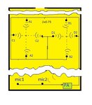
what about of the placement of speakers ?
Speakers should be positioned and directed so that the sound is arriving at the audience from the front site or diagonally, but not from behind.
 

i used audacity ....
That placement was my proposal how to change things for the future. Now they are mounted only 2 speakers, C1 and B2.
I was thinking that if they are pairs of speakers pointed toward each other (and at same height) like in drawing , somehow the sound waves cancel each other in the middle where people are
 
Last edited:

If sound waves are with opposite phase then they cancel. Two or more speakers are supposed to be wired so that they all produce the same phase then the sounds add, not cancel.
You want all speakers to be pointing towards the listeners and away from the priest. The speakers will produce less feedback if they are on the pews in front of the listeners, not up high.
 

Attachments

  • church speakers.jpg
    church speakers.jpg
    179.8 KB · Views: 112

:wink: , for now we order the materials .. we will place them lather
I found 3 microphones there , there is one that produces less feedback . Still PHANTOM type . There is one that produces background noise , the goose neck monacore type. I will try to replace the preamp from it. I'll build one myself :-D
 

Maybe you have all 3 microphones turned on at the same time causing more feedback and echoes.
Some microphone preamps have voice switching so that they turn on a microphone only when a voice is nearby. Then when the priest is talking only his microphone is automatically turned on and the other microphones are automatically turned off and do not produce feedback and echoes.
 

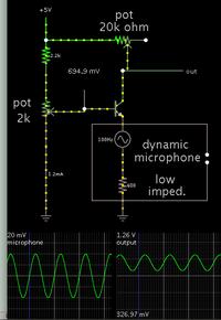
no that's not it. Microphone selection is done manually . No mike is left on when not used . I tested that mike individually , someone worked around that little board with 1 tranzistor .Something i don't get is about that schematic. i tried to put it down to paper and it seemed to be connected in common base connection with lot of RC filtering . I'll try to replace with a simple common emiter connection mode amp. Maybe i'll try with germanium type tranzistor . Found a few NP russian type tranzistors
 
Last edited:

We don't know what that "little board" is connected to and what it does. Is it a mic preamp?
Why use a noisy distorted old-fashioned germanium transistor?
Why doesn't the PA amplifier have a microphone preamp?
 

yep , it's preamp . I mentioned somewhere at the beginning , don't know which post . I just re soldered wires and taught that ok .
I have good experience with germanium tranzistors actually i consider them less noisy than silicium . I used AC and EFT type , it's truth with electrodinamic mike not electret .....
PA has selectable line preamp or mike preamp for each channel , also equaliser . Somewhare at the beginning don't know which post , we found even datasheet
 

someone worked around that little board with 1 tranzistor .Something i don't get is about that schematic. i tried to put it down to paper and it seemed to be connected in common base connection

Perhaps this is similar to the mic pre-amp?

Common base operation is useful when your source is low-impedance and generates its own voltage. Such as a dynamic microphone. (I forget what type you have.)

 
Last edited:

Status
Not open for further replies.

Similar threads

Part and Inventory Search

Welcome to EDABoard.com

Sponsor

Back
Top