Continue to Site

Welcome to EDAboard.com

Welcome to our site! EDAboard.com is an international Electronics Discussion Forum focused on EDA software, circuits, schematics, books, theory, papers, asic, pld, 8051, DSP, Network, RF, Analog Design, PCB, Service Manuals... and a whole lot more! To participate you need to register. Registration is free. Click here to register now.

Eliminate Feedback Oscillations in PA Audio Circuit

Status
Not open for further replies.
One ECM-500 mic is a gooseneck electret cardioid type with a 600 ohm output produced by its Jfet that is powered from a 1.5V AA battery cell. Another mic is a "phantom" powered condenser type.
The cardioid pattern is directional so it should reduce feedback unless it is pointing towards a speaker at one side.
 

yep , that's the equipment , ecm500 has 2 bateries. One of the 2 phantoms has something . two mikes in total are enough ..
Oh and i found 2 wireless microphones also , without receiver ;-)

- - - Updated - - -

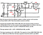
Meantime i draw a little circuit , I want to make the ecm mike to connect like phantom. (so both mikes connect to whatever input, all selected for phantom)
I know this is like opening Pandora's box on this forum :laugh: : Can anyone tell me the values of the rezistors around the tranzistor ?
I admit, i found some values myself , not shore about base resistor for this
preamp.jpg
Thanks
 
Last edited:

Oh and i found 2 wireless microphones also , without receiver ;-)

There might be a chance these transmit on commercial FM band. If so then an ordinary radio serves as a receiver.

Though I have not seen these available in the USA, I did see one that came from Europe. It had to be tuned to a vacant area on the FM band.

---------

Edited to add: 'Mister Microphone' was a store-bought toy version in the US. Ten dollars or so.
 

If the phantom voltage is 48V then I think the 5V regulator will have an input as high as 47V and will quickly burn out. TI recommends 25V max. The 1k resistors should be 27k.
You should never bias a transistor with only one resistor because it has a range of hFE. Do it like this:
 

Attachments

  • electret mic converter.png
    electret mic converter.png
    60.3 KB · Views: 97
  • Like
Reactions: zsolt1

    zsolt1

    Points: 2
    Helpful Answer Positive Rating
Since the phantom voltage is only 18V to 21V then the 1k resistors are fine.

The value of a coupling capacitor is calculated by 1 divided by (2 x pi x R x f) where f is the -3db cutoff frequency. I selected 50Hz and the resistance is the 100k base resistance of the transistor (the 1k emitter resistor x the minimum hFE of the transistor) parallel with the 33k and 39k biasing resistors that are effectively in parallel then the total resistance is 15k.

ok i get the cap , i never studied electronics in school so its clear something i don't see :
Is the 100K impedance considered between base and emiter ? actually base and gnd ?
How are the 39k and 33k in paralell ? related to what ? the 100k impedance somehow ? I see them as voltage divider to supply the base (seting the PSF (punctul static de functionare ) , in my language is traduced somehow like Static Point of Functioning)

Oh , and could you explicit the formula ? do you get it by equaling capacitive ractance with RC time constant , i'm so out of hardware calculations now days :lol:
 
Last edited:

You do not seem to understand my suggestions to date with your responses.

1) You do not have and need noise cancelling mics or twin mics acting as differential noise cancelling.

2) the speakers must never aim towards the mic and should be overhead aming down towards the middle so the path & dispersion loss is more balanced from front to rear.

The SPeakers MUST both be in phase so there is no "hole in the middle" sound effect. ( but the twin mics at each location are out of phase so they detect in the middle and cancel far field. if balanced.
This resullts in more equal level
THey do not cancel from being out of phase.
THey cancel from being exactly equal level AND out of phase.

Imagine the speakers are floodlights that must not illuminate the two mic locations and give even spread of light from front to back and left to right.

At the US festival in '82 they had 400kW of Rock stereo audio power above the stage and another 100kW on scaffold towers delayed so the sound was in phase at that distance. Perfect sound from 100m to stage and then 1km away from stage at the top of the bowl-shaped park with 1/2 million people.
Never any feedback.
 
Last edited:

I agree all speakers need to be in phase. The reason is there is an uncomfortable auditory sensation when sitting equidistant from speakers that are 180 deg out of phase. It's not a terrible fault considering how many things need to be right for us to have good sound quality in a PA system. But audiophiles will detect that the speakers are out of phase, and they will tell you a speaker's wires need to be reversed.
 

Is the 100K impedance considered between base and emiter ? actually base and gnd ?
I explained it. The base to emitter impedance of a transistor is its hFE (the minimum is 100 for the 2N3904 that I selected) times the emitter resistance (here it is 1k) so it is 100k.

How are the 39k and 33k in parallel ? related to what ?I see them as voltage divider to supply the base.
The positive supply has a very low AC impedance to ground. One resistor goes to ground and the other resistor goes to the positive supply so in AC they are in parallel.

Oh , and could you explicit the formula ? do you get it by equaling capacitive ractance with RC time constant ?
I told you the formula for the capacitor value above so its reactance is the same as the resistance it feeds at the frequency you want to be the -3dB cutoff frequency.
 

I explained it. The base to emitter impedance of a transistor is its hFE (the minimum is 100 for the 2N3904 that I selected) times the emitter resistance (here it is 1k) so it is 100k.


The positive supply has a very low AC impedance to ground. One resistor goes to ground and the other resistor goes to the positive supply so in AC they are in parallel.


I told you the formula for the capacitor value above so its reactance is the same as the resistance it feeds at the frequency you want to be the -3dB cutoff frequency.

hehe i got you guru :wink:
i found out myself , google says that coupling caps are calculated from the perspective of a HPF
lpcap.png
So this is where you have that formula :-D

oh , and what if the emiter rezistor is 0 ohm . Is the input impedance really 0 ?
 
Last edited:

You do not seem to understand my suggestions to date with your responses.

1) You do not have and need noise cancelling mics or twin mics acting as differential noise cancelling.

2) the speakers must never aim towards the mic and should be overhead aming down towards the middle so the path & dispersion loss is more balanced from front to rear.

The SPeakers MUST both be in phase so there is no "hole in the middle" sound effect. ( but the twin mics at each location are out of phase so they detect in the middle and cancel far field. if balanced.
This resullts in more equal level
THey do not cancel from being out of phase.
THey cancel from being exactly equal level AND out of phase.

Imagine the speakers are floodlights that must not illuminate the two mic locations and give even spread of light from front to back and left to right.

At the US festival in '82 they had 400kW of Rock stereo audio power above the stage and another 100kW on scaffold towers delayed so the sound was in phase at that distance. Perfect sound from 100m to stage and then 1km away from stage at the top of the bowl-shaped park with 1/2 million people.
Never any feedback.

hi Sunny
i don't know about point 1 , i didn't bring them in discussion . Differential twin mics was what you proposed somewhere in the first replays , i'm just curious what is ...
The second point is confusing , are you talking about my drawing ? if so there is no speaker pointing to the microphone
Ps i made audacity measurement :-D i have resonance at 2K, 3K,4K, 5K the armonics above that have almost no considerable amplitude
 

oh , and what if the emiter rezistor is 0 ohm . Is the input impedance really 0 ?
I was waiting for you to ask that. Since voltage gain is Rc/Re then the gain can never be infinity, it is restricted by the emitter resistance.
The emitter of a transistor has an internal series resistance that is explained somewhere. Its value is calculated as 25mV divided by the emitter current but I never calculate it when I need to know the emitter resistance, instead I look at the graph of typical input impedance of a 2N3904 transistor on its datasheet at various currents. The internal emitter resistance is the input impedance divided by the AC hfe (not the DC hFE).
 

Status
Not open for further replies.

Similar threads

Part and Inventory Search

Welcome to EDABoard.com

Sponsor

Back
Top