Continue to Site

Welcome to EDAboard.com

Welcome to our site! EDAboard.com is an international Electronics Discussion Forum focused on EDA software, circuits, schematics, books, theory, papers, asic, pld, 8051, DSP, Network, RF, Analog Design, PCB, Service Manuals... and a whole lot more! To participate you need to register. Registration is free. Click here to register now.

Differential probe build

Status
Not open for further replies.

Swend

Full Member level 4
Full Member level 4
Joined
May 14, 2019
Messages
237
Helped
10
Reputation
20
Reaction score
9
Trophy points
18
Location
Roskilde, Denmark
Activity points
2,304
Hi Friends

I need a differential probe, something simple and rugged that is known to work and has minimum 100MHz bandwidth. I like this one https://www.eevblog.com/forum/projects/my-first-project-low-cost-differential-probe/

However I'm a bit worried if I can make the PCB layout, because it looks like it was made by a person that knows something about RF, which I don't.

So the question is what should I take into consideration when making the layout?
 

Differential probe is a rather general topic. Beside bandwidth, you want to specify input impedance, common mode range and common rejection ratio before you start any actual design work.

The original design posted in the blog would be useless for most differential probe applications that I know. Either you have a rather special application in mind, or you don't yet realize the limitations of the design.
 

Differential probe is a rather general topic. Beside bandwidth, you want to specify input impedance, common mode range and common rejection ratio before you start any actual design work.

The design is basically the AD8129 and I just skimmed over the specs which seemed reasonable to me.
High speed
AD8130: 270 MHz, 1090 V/μs @ G = +1
AD8129: 200 MHz, 1060 V/μs @ G = +10
High CMRR
94 dB min, dc to 100 kHz
80 dB min @ 2 MHz
70 dB @ 10 MHz High
input impedance: 1 MΩ differential Input
common-mode range ±10.5 V
Low noise
AD8130: 12.5 nV/√Hz
AD8129: 4.5 nV/√Hz
Low distortion, 1 V p-p @ 5 MHz
AD8130, −79 dBc worst harmonic @ 5 MHz
AD8129, −74 dBc worst harmonic @ 5 MHz

And the problem is that I need four of those probes in a jiffy and I would rather not do additional design work, because I have some other pending tasks that I would like to finish before I leave and that requires differential probes. It would be nice if there were time to deep dive into the subject as I find it interesting and educational, but as you say it's a rather general topic so there must exist working designs, this is also a candidate https://blog.weinigel.se/2016/02/26/ghz-differential-probe.html

The original design posted in the blog would be useless for most differential probe applications that I know. Either you have a rather special application in mind, or you don't yet realize the limitations of the design.

I think it is a bit of both, but mostly the latter.

Could you please exemplify it's uselessness?
 

O.K., if you can live with AD8130 common range, this is surely an option. I have used it in a number of design, particularly high MHz current sense. +/- 10V is only achieved with high supply voltage, of course. AD8129 has very unpleasant supply current with input overload, you should consider it if overload can happen in your application.
 
  • Like
Reactions: Swend

    Swend

    Points: 2
    Helpful Answer Positive Rating
O.K., if you can live with AD8130 common range, this is surely an option. I have used it in a number of design, particularly high MHz current sense. +/- 10V is only achieved with high supply voltage, of course. AD8129 has very unpleasant supply current with input overload, you should consider it if overload can happen in your application.

I guess I can, I will be using a resistive divider for voltages higher than that. And i think that I require consistent repeatable measurement results over calibrated and exact.

I will just have to be cautious not to overload the input.

But what about the PCB layout, any caveats I should be aware of?
 

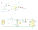
Here is my first version of the probe, any objections to my design?

I'm uncertain about at least two things

1. Will the AD8130 clip the input signal with +/- 9V supply? Personally I don't think so.

2. Since I'm using NiCd batteries I connected the charge USB plug directly to the battery, and I figured if I use a phone charger then there will probably not be any smoke even though there is no charge control.

scope-probe-1.png
 

First, since your probe ground is basically tied directly to U1 (only 470R) your common mode voltage is limited to the 9V supply rails. Is that acceptable? I expect differential probes to have common mode ratings equal or greater to their differential ratings.

And I'd like to see your AD8130 input pins have common mode clamps in addition to your differential clamps (zener type or diodes to the rails).

I wonder if you need to short scope ground to USB ground. Seems you could break that direct connection (perhaps clamp them to each other for protection) and reference your amplifier output to scope ground for some additional ground common mode rejection.

An alternative scheme could use a 5V to +/-9V isolated DC-DC instead of your charge pump.

Finally I'll recommend having linear regulated power. This chip has charge pumps and regulators.
https://www.analog.com/en/products/ltc3265.html
 
  • Like
Reactions: Swend

    Swend

    Points: 2
    Helpful Answer Positive Rating
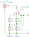
Doesn't work this way, a double pole switch is needed. Reconsider!

dvider.PNG
 
  • Like
Reactions: Swend

    Swend

    Points: 2
    Helpful Answer Positive Rating
First, since your probe ground is basically tied directly to U1 (only 470R) your common mode voltage is limited to the 9V supply rails. Is that acceptable? I expect differential probes to have common mode ratings equal or greater to their differential ratings.

And I'd like to see your AD8130 input pins have common mode clamps in addition to your differential clamps (zener type or diodes to the rails).

I'm sorry but I don't understand how U1 would ever experience common mode voltages on it's input, wouldn't that require that the scope gnd is connected to circuit gnd somehow?

The 470R's are just to limit current when the 5V zeners break down.

AD8130 has max 5V differential voltage, and starts clipping at 5.6V

reference your amplifier output to scope ground for some additional ground common mode rejection.

What a splendid idea, thanks.

An alternative scheme could use a 5V to +/-9V isolated DC-DC instead of your charge pump.

Finally I'll recommend having linear regulated power. This chip has charge pumps and regulators.
https://www.analog.com/en/products/ltc3265.html

LTC3265 is $10 and the MAX865 is $3, is it worth the 7 bucks? But I agree the LTC3265 is probably less noisier with that post-LDO.

- - - Updated - - -

Doesn't work this way, a double pole switch is needed. Reconsider!

Duh... silly me, thanks.
 

Your circuit is sending the "Scope Probe" ground (BNC pin 2) directly to U2 (through 470ohm). If your scope probe ground is NOT referenced to U2's ground then you have big problems. And having different grounds is the point of a differential probe...


$7 isn't bad considering the cost and space of discrete linear regulators. If you don't add linear regulators at least add some additional filtering after the capacitive switcher and try to keep that in its own area of the board.
 

And having different grounds is the point of a differential probe...

Yes indeed.

Your circuit is sending the "Scope Probe" ground (BNC pin 2) directly to U2 (through 470ohm).

Yes but it's still a differential input signal, so I don't quite understand your point here?

If your scope probe ground is NOT referenced to U2's ground then you have big problems.

If I connect "scope probe ground" to U2's ground which is connected to scope ground, then I believe the probe becomes single-ended again and defeats the whole purpose of a differential to single-ended conversion?

$7 isn't bad considering the cost and space of discrete linear regulators. If you don't add linear regulators at least add some additional filtering after the capacitive switcher and try to keep that in its own area of the board.

You are right and I was just about to change the design when I saw min supply voltage is 4.5V, and with 4.5V batteries it does not leave much headroom, whereas the MAX865 in min 1.6V.
 

Again consider a real scenario:

1) The ground symbol on your schematic is connected to earth through the oscilloscope -> Call it 0V
2) You connect your "Scope probe ground" to something that's 50V
3) Result: R6 and/or U2 blows up.

Point being you need to have high impedance dividers on both inputs to your amplifier since either input can be at a high voltage in relation to your amplifier's ground.

Yes I see that scenario easily happening to someone that is not considerate. But that requires that the scope is earthed (as in the planet earth) and that "something" is earthed too. Obviously if you are careless you can always blow your equipment, or worse - incorrect measurement results. For that purpose I have adapted the old adage "measure twice, cut once" to electronics: "Think twice, measure once".

The AD8130 is U1 btw.

If the 'something' isn't earthed then you don't need the differential probe. You can connect your earthed scope probe anywhere you want on an isolated circuit.

I'm curious where you think you need a differential probe.
 

If the 'something' isn't earthed then you don't need the differential probe. You can connect your earthed scope probe anywhere you want on an isolated circuit.

I'm curious where you think you need a differential probe.

Yes you can connect ONE OF your earthed scope probe anywhere you want on an isolated circuit. Since I have four channels I can't connect all four probes where I wan't, because gnd/earth is interconnected on the scope. My scope is also isolated/floating, even though I still can't connect all four probes where I want because gnd/earth is interconnected on the scope. I'm currently working on a isolated circuit that in addition has 24 isolated nets, and it is impossible to measure two signals simultaneously without a diff probe?

So what about the second stage output filter? Where/how do I get the value for the angular velocity? Or perhaps you know some easy rule-of-thumb for ballpark-ing the filter?
 

So your scope isn't earthed. It doesn't matter.

The scope ground (and your differential probe circuit ground) is at potential A
Circuit B is at potential B
Circuit C is at potential C

If A, B and C could be the same potential you could use your scope as-is right now.

Since they're not you need a differential probe that can tolerate the common mode potential differences between A, B and C.

But your circuit as drawn can't tolerate more than ~9V between it's ground and the circuit its measuring.

Now I'm confused, A,B and C are all floating that means they have no common reference, if they have no common reference there can be no common mode potential differences between A, B and C, am I right or wrong?

And if A, B and C could be the same potential I could NOT use my scope as-is right now if I wanted to measure three differential signals (I could perhaps measure two (with four probes) if I make the scope subtract one from the other. But my scope can't make two subtractions at once, and the result of the subtraction can not be saved.
 
Last edited:

Additionally, you must add a trim capacitor to frequency compensate your dividers, otherwise the stray capacitance will form a low-pass filter.
 

Now I'm confused, A,B and C are all floating that means they have no common reference, if they have no common reference there can be no common mode potential differences between A, B and C, am I right or wrong?

And if A, B and C could be the same potential I could NOT use my scope as-is right now if I wanted to measure three differential signals (I could perhaps measure two (with four probes) if I make the scope subtract one from the other. But my scope can't make two subtractions at once, and the result of the subtraction can not be saved.

I'd say the opposite: If they don't have a common reference then there is nothing preventing them from having a common mode potential difference. And if they're not galvancially isolated but you call them 'floating' that implies they do have a common mode potential difference.


But we may be arguing over definitions. I'll go back to the problem: Your circuit can't measure a signal that has greater than ~9V between your differential scope probe ground and the oscilliscope ground. In my mind that's hardly a good differential probe and you havn't made a convincing case that this is actually ok in your application. Particularly given that you want to measure high voltages.

I think you need to diagram the whole picture including the scope and the circuits connected too it and think through what the potentials of each node are in relation to your scope ground (which is your differential probe circuit ground too).
 

Status
Not open for further replies.

Part and Inventory Search

Welcome to EDABoard.com

Sponsor

Back
Top