Continue to Site

Welcome to EDAboard.com

Welcome to our site! EDAboard.com is an international Electronics Discussion Forum focused on EDA software, circuits, schematics, books, theory, papers, asic, pld, 8051, DSP, Network, RF, Analog Design, PCB, Service Manuals... and a whole lot more! To participate you need to register. Registration is free. Click here to register now.

Build easy MPLAB-6 ICD-2 for PIC18F2550

Status
Not open for further replies.
icd2 rar

SAR said:
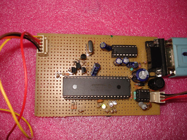
This is an In-Circuit-Debugger compatible to Microchip's new MPLAB-6 IDE (ICD2). It was designed to use as few as possible and only common parts while providing basic functionality sufficient for home use.

**broken link removed**

SAR

I don't already have a programmer. Not even a ICSP. So will I need to get my 16F876A programmed with the bootloader beforehand. If so could you help me with avery basic programmer that can be mounted on a project board.

Thanks.
 

ccs icd pic12f683

Andy_123 said:
Here is schematics PDF and board

I got FT232RL from Mouser - they have it in stock
They also have all other components in stock, including 16F876

what is the other DIP IC in your design?
 

programs of dspic30f6014

what is the other DIP IC in your design?
Complete design posted about 15 posts higer.

Large chip is PIC
8 pin chip is OP AMP, LM358 or any other you can find - not critical
Last chip is DCP010515 voltage converter
 

clone mplab icd 2

Hi, i built the ICD2-clone (stolz-design) also.
I use MPLAB7.3 and connect the ICD to com2 given by usb-serial converter.
But, everytime connect the ICD, these MPLAB errors occur
Code:
ICD0021: Unable to connect with MPLAB ICD 2
MPLAB ICD 2 Ready
Could it by a problem generated by MPLAB ??
I know, with this message it could be nearly everything, but i tried to change the comPort, used different driverVersions, changed the settings in the Portdialog, and so on.
I think it could also be a communication problem between the FTDI and the PIC, but I want to be shure that there´s no MPLAB problem.
 

icd2 16f firmware

Hi,
I have pic16f877a based icd2. First I worked fine but know it has a problem: when I connect to ICD2, error: lost communication.
Anyone has any ideas?
Thanks in advance
 

pic homemade icd usb

hi,
I too have similar problem with 877a based icd2, It connects alright but fails to download operating system in mplab 7.31 and higher.I do not have a solution yet.
 

tusb3410 *./rar

i have build a ICD2 USB Clone PIC18F4550 and PIC 16F877A but its not working what can ido Can any one help


OS XP SP2

MPLAB 7.10

Error :
Connecting to MPLAB ICD 2
ICD0019: Failed to open communications: Non-existent port
ICD0021: Unable to connect with MPLAB ICD 2
MPLAB ICD 2 Ready

Can any one help

Added after 42 minutes:

I have attached the photos of the ICD it was designed using the datas i have attached
please any one help me !!
 

potyo icd2 usb device not recognised

I want use pic18f2455 Usb Programmer
 

usb pic18f +pullup

for PIC18F4550 set mclr internal or add rezistor to mclr from 5v
Pin1(Pic18f4550) ---- 4.7k ----- 5vcc
 

sllc251.zip

hai here i have attached the Screen shot of configuration word of PIC18F4550 i have enabled the MCLRE , if i plug in to usb no chang is happening windowsXP is not identifing or making sound for the usb device
 

mplab for icd2

I have decided better to use an RS232 ICD2 Clone and build it using PIC16F877A and circuit of h**p://www.stolz.de.be/ and loaded BootLoader16F877A.HEX and tested with MPLAB7.10 and the PIC18F4550 as target , at first these error messages are shown

Connecting to MPLAB ICD 2
...Connected
ICD0082: Failed MPLAB ICD 2 operation
MPLAB ICD 2 Ready

and i downloaded the BL010101.hex manualy from the ICD Directory in MPLAB7.10 and the operation sucess!!!!
then again i connected the following results from the ICD2

Connecting to MPLAB ICD 2
...Connected
Setting Vdd source to target
Target Device PIC18F4550 found, revision = a1
...Reading ICD Product ID
Running ICD Self Test
... Failed Self Test. See ICD2 Settings (status tab) for details.
MPLAB ICD 2 Ready

then i checked for the status tab, and found that i Missed the connection to RA1 for the target VCC/VPP so the self test has been reported for MCLR GND as HIGH and i finished the connetion and sucessfuly completed the ICD2 i am going to test debuging a PIC16F876A thank you all in this forum:D:D


75_1157026432.jpg
 

build own icd2

Hi,
@mmnetmohan.
I use almost the same project like in your first posts. For USB. So, I will upload here, but keep in mind that it is NOT my project.

Also, for the win2003, in the other topic work very good the Potyo tip, page 16. Just for who needs and don't find that.

Regards,


L.E.- for your problem use the tip above! For MPLab 7.41 and XP SP2 use the \MpLab\MpLabIDE\Utilities\mpusbIRU.exe to preinstall or update the driver. When connect to USB, the two led's must light ON. (power and USB) Usually you must to remove the L2 and just put a direct connection, because sometimes the voltage on pins 11/12 is lower than 4,5V. And at the exit ICSP connector check the resistors with the schematic, not with the compnents layout, because there's some errors. I work with MCLR ON, it make no difference. And don't forget to put a lot of 100nF cap's everywhere on the Vcc line.
Good Luck!

L.L.E. - I put in the archive also the two files witch ask ICD2 for when first load.
 

failed mplab icd 2 operation com1

i haved checked the sch twice but nothing improvement

Iam using IBM PC with 6 USB ports (4 at Back and 2 at front) i have no usb device other than this i have pluged all the ports are free , when i plug in the Power Led and USb Led was glowing and when i touched the PIC18F4550 the USB Led goes OFF and i remove the hand agail it Glows , i have soldered a Pullup resistance from MCLR of 4550 to VCC this time when i pluded the ICD the POWER and USB Leds Glow when i touched it Still Glows. But By windows Does't even sounds a sound when i plugin to the Port i have dowenloaded the Firmware you provided , i have nade the board like i posted in the this forum. can you Suggest me what could be wrong with my ICD
 

vista icd2 mplab cannot connect

Hi, I'm new on this forum...

I have made the ICD 2 of this web, h**p://www.stolz.de.be/ , and I need some information about number pins of RJ-11 connector, because I only have information about name of pins, Target MCLR, Target PGC, Target PGD, and I need know what Pin is Target MCLR, and so on....

Thanks,
 

debuger ic2

hi link_led watch this page youll find the ICD header information , and how to connect to the target Devices and Pin informations

h**p://www.microchip.com/stellent/idcplg?IdcService=SS_GET_PAGE&nodeId=1406&dDocName=en010046&part=DV164005
 

6 pin 6 led mplab

Hi,
Sorry for the delay...
Listen, if the USB led is ON, is the first good step. At this moment you must see the instalation of the Microchip Tools/Microchip MPLAB ICD2 Firmware Client. Try to use
\MpLab\MpLabIDE\Utilities\mpusbIRU.exe to preinstall or update
.
It is important whay is the answer you get. Also, witch OS you use exactly?
For me seems a instalation/software problem, not ICD2. If the LED glows, the device enumerate on the usb. Now it is important to see why it is not recognized.
Be careful, sometimes when you unplug the ICD2 from USB, the first memory zone of the 18F4550 is cleared. The next connection the USB led will not glow! Need in this situation re-write the boot for 4550.

Please, if you get unstable behaviour, Try to put everywhere 100nF caps, and use some solder on the ground copper. The enumeration must basically work even without 16F877A, or MC. BTW, you have the 12,75Volts on the Schottky diode?

Good Luck! Let us know, please!
Regards,
 

icd2 pcb code

Can we program all PICs with this ICD2? or it's just for debugging?
 

icd2 reflash 16f877

hi

i i have an improvement, i debuged the ICD Debugger for two weeks , i have updated all the FW found in this Forum, and found nothing work, because its not FW fault , its problem with my board, so i decided to build a prototype with only the
minimum components

1 X PIC18F4550
2 X 4.7 K - 1 for Pullup on RB7 and 1 for Pull down on RA4
1 X 20 Mhz for OSC
1 X 470nf @ (RC3) Vusb to GND

reset
1 X 0.1 uf for MCLR to GND and
1 X 10 for MCLR to VCC and
1 X reset button for MCLR to Gnd for reset

vcc
1 X 1000 uf /16v to vdd to vss pin

D+ to usb D+
D- to usb D-

this is to check the fW for PIC18F4550

i assembled the Prototype and connected to PC and and windows XP SP2 said that "USB device not Recognized", so i have an improvement that windows is showing mercy to me, then i press the reset button on the prototype board for 2 -3 seconds and released , finaly windows said

"USB device found"
:D

"microchip firmware client"

and it asked to update the driver using a wizard

and i select the driver path and finaly the MCp fW client was installed on my PC

is this type of problem any one found!!

when i simply plug in windows is telling "USB device not Recognized"
but if press reset button and plug the usb Cable and released after 2 Seconds windows is Recognized the Device

thank u PiCS for FW and Sch, PCB
thank u Pavcostel for your clue to eleminate the other components and to found out the problem

regards

mmetmohan

71_1157610392.JPG


74_1157610491.JPG
 

pic18 without mclr

Good job! Easy solution and practical!
Try to program PWRT - on. Usually I do that on all my small experiments. Also, maybe you have some ripple from the power supply on the PC. Just for test, use some extra electrolithyc Capacitor and a small inductor on the +5V line from USB to ICD2. Some filter, LC. But carefully measure the Vcc on pins 11 and 12 on the 4550!!!
Must not drop! Maybe is better to use two 470uF instead of 1000 uF...Up to you.
Anyway, your problem is due to some interference/electrical disturb on the power line from USB. Try also a USB cable with a filter ( ferrite ring).

Good Luck!

Regards,

L.E. - i see in your photo that you don't use a connector for USB! Try to have maximum 10cm of wire, otherway's you will get trouble. As short as possible!
 

Status
Not open for further replies.

Similar threads

Part and Inventory Search

Welcome to EDABoard.com

Sponsor

Back
Top