Continue to Site

Welcome to EDAboard.com

Welcome to our site! EDAboard.com is an international Electronics Discussion Forum focused on EDA software, circuits, schematics, books, theory, papers, asic, pld, 8051, DSP, Network, RF, Analog Design, PCB, Service Manuals... and a whole lot more! To participate you need to register. Registration is free. Click here to register now.

Boost Converter analysis

Status
Not open for further replies.
Did you see my video?
It gives variable output. Isn't should be fixed?
It gives me variable input and output current. Are they should not be fixed?
I am providing 12V of peak to peak voltages to the MOSFET. Are these not high enough?
I read somewhere that when selecting MOSFET for boost converter then the MOSFET Vds voltage must be greater than the load voltage plus the diode drop. For example, if load voltage is 5V and Schottky forward voltage is 0.4V then 5+0.4=5.4V. So MOSFET of Vds=10V is good to use. But the BUZ31 has Vds=200V. So is it OK?

Are not these referred to the problems in the circuit sir?
Is my circuit good?

Thank you for your help teacher.
 

It gives me variable input and output current. Are they should not be fixed?
I see in the video that they vary as you change the gate drive voltage, not surprising. The gate voltage is probably too low, but I can't see this clearly from this toy style simulator results.

A real boost converter must use a feedback loop with variable pwm duty cycle. Your simulation can be understood as a demonstration of boost converter working principle, but not as a real design prototype. In my view it's pointless to discuss design details based on this simulation.
 
  • Like
Reactions: tpetar

    tpetar

    Points: 2
    Helpful Answer Positive Rating
@BradtheRad
Your circuit is working much good. You know, I tried your one and it is working well. But why not mine.

I experimented with the frequency until I found a suitable speed to drive a 6uH coil. This is about 300 kHz.

Your capacitor value of 1 uF is barely able to power the load during the gap between current bursts. Instead I used a value of 10 uF. It stores more juice as it gets a burst of current during switch-Off time. Hence it can power the load during the idle gaps.

You are correct that the mosfet must endure a higher volt level than your desired output. If the load is disconnected, the volt level can quickly soar to several hundred volts.

- - - Updated - - -

Which simulator will you recommend me then?

To assist in getting a grasp on switch-coil converters...

It helps to watch an interactive animated simulation.

I devised a tutorial simulation using your component values.

If you click the link below, it will open the simulator at falstad.com/circuit, load my schematic (post #39), and run it on your computer.

https://tinyurl.com/nyk3j4a

Click the switch at left to start the power cycle. Let up on the switch to go to the output cycle.

Watch how the coil behaves. It is at the heart of the action. Your aim is to turn the switch on and off so as to send 500 mA through the 5V battery (load) at left.

After a while you will find a tempo which provides the desired output.

You can also cheat by clicking the switch which selects the clock control. It is set to provide pulses at the proper rate.

You can change the smoothing capacitor value, by right-clicking it and selecting Edit.
 
  • Like
Reactions: Eshal

    Eshal

    Points: 2
    Helpful Answer Positive Rating
Hello sir,
I have found this statement about boost converter but don't know how to use it or how to estimate ripple current.
We can find inductor value from the equation below,
L = [Vin(min) * D] / [fs * Irip]
where, L = inductor,
Vin(min) = minimum input voltage
D = Duty cycle
fs = switching frequency
Irip = Ripple current

If designer doesn't know Irip then he can't find inductor value, so he can use this equation. A good estimation of inductor ripple current is 20% to 40% of the output current, below
Irip = (0.2 to 0.4) * Iout(max) * Vout/Vin

Now I want to know how to use this equation.
Let say I am choosing 0.4,
Iout(max) = 500mA
Vout = 5.2V
Vin = 3V

Now using formula,
Irip = 0.4 * 500m * 5.2/3
Irip = 0.4 * 500m *1.733
Irip = 0.4 * 0.866
Irip = 0.34666mA
Irip = 346.66mA

Did I calculate in right way? Is my estimation for Irip right? Answer is correct, huh????
 

Both the formulae that you've written have already been explained in the thread,in a slightly different form.

The formula, Irip = (0.4)* (Iout * Vout)/Vin is similar to the way Irip was calculated in post #13.

Vout * Iout = efficiency *(Vin * Iin).

Thus your formula reduces to Irip = 0.4 * Efficiency * Iin.
You've used it as 100% efficiency,otherwise it's okay.
 
Last edited:
  • Like
Reactions: Eshal

    Eshal

    Points: 2
    Helpful Answer Positive Rating
Yes, yes very true.
You have told me. I remember. But want to ask one thing more, I have calculated it for 100% and found Irip = 346.66mA. But we all know it is difficult to get 100% efficiency of the boost converter. They why did we calculate Irip for 100% efficiency? Even Texas Instruments makes Boost Converter IC which provides 89% efficiency. So did they calculated Irip for 100% efficiency too?

And again I ask you that my calculated value of Irip is correct 346.66mA?

Thank you sir,
 

346 mA is not unreasonable.

My simulation has several hundred mA of ripple through the coil.

Furthermore when charging a battery, the load impedance is much less than 10 ohms. It is a fraction of an ohm. (Notice this includes the capactor.)

There is also the battery voltage to overcome.

Therefore the resulting waveforms may be different than when your test load is a 10 ohm resistor. The resulting ripple Amperes can be different.
 
  • Like
Reactions: Eshal

    Eshal

    Points: 2
    Helpful Answer Positive Rating
Inductance variations (by production lot, current, temperature) will be usually larger than the difference caused by taking account to the converter efficiency. In so far the discussion isn't of much practical relevance.
 
Teachers, your explanations are very useful. They lead me to construct my own Boost Converter on my own.
So I am designing. Here is what I have done yet so far, I have calculated Inductor value for Iout(max)=0.5A, Vo=5.2V, Vs=3V, fs=500KHz

For this, I first calculated Irip as,
Irip = 0.4 * Iout(max) * Vo/Vs
Irip = 0.4 * 0.5 * 5.2/3
Irip = 0.4 * 0.5 *1.733
Irip = 0.4 * 0.866
Irip = 346.66mA
Then I calculated L value as,
L = [Vs * (Vo - Vs)] / [Irip * fs * Vo]
L = [3 * (5.2 - 3)] / [0.34666 * 500000 * 5.2]
L = [6.6] / [901316]
L= 7.322uH

Now, I will calculate value for output Capacitor (Cout)
I found this note somewhere on internet about the selection of Cout for Boost Converter,
OutputCapacitorSelection
Best practiceis to use low ESR capacitors to minimize the ripple on the output voltage. Ceramic
capacitors are a good choice if the dielectric material is X5R or better

the following equations can be used to adjust the output capacitor values for
a desired output voltage ripple:
\[Cout(min) =\frac{Iout(max) * D }{ fs * Vripp}\]
where,
Cout(min) = minimum output capacitance
Iout(max) = maximum output current of the application
D = duty cycle
fs = minimum switching frequency of the converter
Vrip = desired output voltage ripple

From the above given equation for Cout(min) I can find out the output Capacitor value.

Now I have following questions,
What should be Vrip so that I could calculate the Cout?
Is my value of L for the given parameters Correct. Huh??
And, how to know which capacitor has low ESR?

Thank you teachers :)

Regards,
Princess

- - - Updated - - -

I agreed to FvM, discussion is not much practical. But I want it to take off slowly. :)
 

What should be Vrip so that I could calculate the Cout?

Whatever device you must power, it can tolerate a certain amount of ripple.

Suppose it needs between 4.9 and 5.1 V. Then your ripple V spec can be 4 percent.

Is my value of L for the given parameters Correct. Huh??

From doing my simulation, 6 or 7 uH is suitable.

A real coil which you build or purchase may not have the exact same Henry value. Therefore you will adjust the frequency and/or duty cycle, in order to obtain the desired output V to your load.

And, how to know which capacitor has low ESR?

ESR becomes more important when a capacitor is required to carry high current back and forth.

ESR is a spec which you might see quoted for new components.

You can also measure it with a special meter (purchased or built), or using a setup involving a low-ohm resistor and a low-voltage waveform generator.
 
  • Like
Reactions: Eshal

    Eshal

    Points: 2
    Helpful Answer Positive Rating
Thank you very much for your reply sir.

I am thankful to you.

Whatever you told me about Vrip. I couldn't get of it so much. In university, teacher doesn't teach us designing of circuits. They tell us working and derivations of the formula. While my perception is that, on this practical level, teacher should teach us designing so that we could able to face industry. But unfortunately this is not the case with students at university, at least at not in our country.

That's why sometime I can't get your wordings because I don't have mind set like you. You have experience in this field while we don't have any experience.
So please tell me how to know that how much vripp should be there for specific application or load. Means I have load a mobile battery. So how much Vrip should be beard by my circuit? you told 4%, why?

And similarly, I am a student of 3rd year in electronics engineering but we didn't listen the term ESR, I read it myself so I am aware of this term some little bit. I don't have meter to measure ESR. So is there any way to find it out anyhow? Or at least you can tell me which capacitor is OK to use for my this Boost converter?

Thank you very very much.
 

So please tell me how to know that how much vripp should be there for specific application or load. Means I have load a mobile battery. So how much Vrip should be beard by my circuit? you told 4%, why?

It depends on what device you wish to power. Some devices require a tightly regulated power supply. Others do not.

Charging a battery does not need tight regulation. It can tolerate a large ripple voltage. However if you control the charge rate by means of voltage or current sensing, then you might wish to smooth the ripple to a smaller amount, say 1%.

I don't have meter to measure ESR. So is there any way to find it out anyhow? Or at least you can tell me which capacitor is OK to use for my this Boost converter?

ESR is not easy to measure, hence it is not commonly diagnosed.

The types which are most likely to develop ESR problems are aging electrolytics.

A new capacitor is likely to have low ESR.

In the event that you find either (a) the output ripple V is higher than expected, or (b) the capacitor is getting hot... You can substitute different capacitors of the same value, as a check.

For cheap methods of testing ESR, try an internet search on:

'99 cent ESR test adapter'
and
'capacitor ESR tester homebrew'
and
'barebones ESR tester'
 
  • Like
Reactions: Eshal

    Eshal

    Points: 2
    Helpful Answer Positive Rating
Hello sir.
How are you?

Thank you for your good reply. I am thankful.
It depends on what device you wish to power. Some devices require a tightly regulated power supply. Others do not.

Charging a battery does not need tight regulation. It can tolerate a large ripple voltage. However if you control the charge rate by means of voltage or current sensing, then you might wish to smooth the ripple to a smaller amount, say 1%.
This statement helped me. I want to know if there is any note on voltage ripple or current ripple so that I could get more knowledge about them.
And this means I can use 4% to 8% (large ripple content) of voltage ripple here for my application. and then smooth it to 1%. Huh???

ESR is not easy to measure, hence it is not commonly diagnosed.

The types which are most likely to develop ESR problems are aging electrolytics.

A new capacitor is likely to have low ESR.

In the event that you find either (a) the output ripple V is higher than expected, or (b) the capacitor is getting hot... You can substitute different capacitors of the same value, as a check.

For cheap methods of testing ESR, try an internet search on:

'99 cent ESR test adapter'
and
'capacitor ESR tester homebrew'
and
'barebones ESR tester'
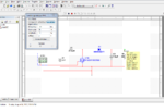
Thank you for this detail explanation. I will ask you as I find something.
Thank you very much sir.
 

designed boost converter.PNG

Here is my designed boost converter.
Finally I have done it. It is not exactly what I want but it is giving me much better result.
You can see I have placed a probe at the output which is showing output voltage V(dc)=5.28V. These are the voltage which I want at the output exactly. But I also want output current I(dc)=0.5A. But it is showing my I(dc)=1.06A. This is the problem. What should I do to reduce the current but other parameters like Duty Cycle, output voltage should not be changed.

I am highly thankful to FvM, BradtheRad and rahdirs, they helped me a lot on this project.

Thank you experts
 

View attachment 94453

Here is my designed boost converter....

What should I do to reduce the current but other parameters like Duty Cycle, output voltage should not be changed.

The remaining option is to insert an ohmic resistance in one or two spots. (Notice that my simulation shows a few tenths of an ohm here and there.)

An easy way is to reduce bias to your switching device (mosfet or transistor).

This method is wasteful and it generates heat. You may need to install heatsinking.
 
  • Like
Reactions: Eshal

    Eshal

    Points: 2
    Helpful Answer Positive Rating
@BradtheRad

Capture.PNG

Thanks for the tip. I have added the series resistor of 0.4ohm and increased the load resistor to 10.4ohm from 5ohm.

You said to reduce bias to the switching device. I didn't get. What do you mean by bias? Do you mean amplitude (which was 10Vp in the post#58)?

Thanks for your help sir.
 

You said to reduce bias to the switching device. I didn't get. What do you mean by bias? Do you mean amplitude (which was 10Vp in the post#58)?

Thanks for your help sir.

Yes, reduce volt level to the mosfet gate, so the device conducts less than maximum current.

However when you do this, the converter loses efficiency, because you are no longer operating the device as a switch, but are using it to create resistive drop (linear mode).

You would maintain the efficiency of your converter, if you reduce the duty cycle instead.
 
Status
Not open for further replies.

Similar threads

Part and Inventory Search

Welcome to EDABoard.com

Sponsor

Back
Top