Continue to Site

Welcome to EDAboard.com

Welcome to our site! EDAboard.com is an international Electronics Discussion Forum focused on EDA software, circuits, schematics, books, theory, papers, asic, pld, 8051, DSP, Network, RF, Analog Design, PCB, Service Manuals... and a whole lot more! To participate you need to register. Registration is free. Click here to register now.

Boost Converter analysis

Status
Not open for further replies.
No battery size was mentioned yet, so nothing to say about achievable output current. Forget about anything below C/LR14 from the start.
 
  • Like
Reactions: tpetar

    tpetar

    Points: 2
    Helpful Answer Positive Rating
See this examples with IC :

LTC3426 - 1.2MHz Step-Up DC/DC Converter in SOT-23
http://www.linear.com/product/LTC3426

3.3V to 5V DC-DC converter Circuit & PCB files provided
http://www.circuitsathome.com/dc-dc/33v-to-5v-dc-dc-converter


2586_app_1.jpg


2586_app_2.jpg


Best regards,
Peter

;-)
 
  • Like
Reactions: FvM

    FvM

    Points: 2
    Helpful Answer Positive Rating
@FvM
No, I don't need any pre-designed step up converter IC. I want to designed my own. Simple but working. Because it is my first designed regarding power electronics.
Last semester I had power electronics subject.

@BradtheRad
Thank you sir. It is really good. Nice view :) I like this simulation.wowwwWW

@rahdirs
So we have designed DC to DC boost converter. Huh?

@tpetar
You have given a link of ready made IC. But I want to designed my own. Whether it is a toy. But should be my hard working.

@all experts!
So finally, I have designed my first DC-DC boost converter. Should I simulate it? I use Proteus. Do I post result of simulation so that you experts could help me further?

Thank you very much. You all are good in practical and theory :)

Regards,
Princess.
 

Benefit from simulating this like designs is small, specially if you making new design and dont know what is result. True and real results only can be achieved with real environment and real parts, usually people see different results. :)

My suggestion to you, when you finish simulation, try this with real parts and compare.


Best regards,
Peter
 
  • Like
Reactions: Eshal and FvM

    FvM

    Points: 2
    Helpful Answer Positive Rating

    Eshal

    Points: 2
    Helpful Answer Positive Rating
Check in software,but i don't know if you should connect it to the Li-ion battery directly.I don't know about LT IC that Peter posted,but the DC/DC LT IC that i used had current limiting in it.
Try testing on any spare batteries.
 
Last edited:

Got it sir.
And I am going to try it with the following specifications on my simulation software Proteus:
L = 6.1825uH
C = 1.6153uF
Vs = 3V
Further, I will use MOSFET and I will use 500KHz frequency to switch it.

After simulation I will post result.

Thank you sir.

- - - Updated - - -

Hello experts!
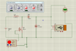
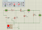
Here is a snap of Proteus simulation.
Capture.PNG
I have used the following
MOSFET.
Signal Generator as a switching frequency driver with 500KHz frequency.
Generic Diode 1N4001
Real Inductor model
Electrolytic capacitor. I used electrolytic capacitor because somewhere I read on high frequency application we should use electrolytic capacitor. And here it is 500KHz.
And Type A female USB connector.

You can see it is showing 5V at the output.
Is there something that you experts think you should tell me?
 

Yes, try this with real parts, and post results, this can be very interesting.

What simulator says what efficiency design achieve ?

One additional thing, general purpose rectifier diode such this 1N4001 cannot be used for this purpose! You need fast schottky with good specification and small voltage drop. And you see simulator says this works. :)


Best regards,
Peter

;-)
 
  • Like
Reactions: Eshal and FvM

    FvM

    Points: 2
    Helpful Answer Positive Rating

    Eshal

    Points: 2
    Helpful Answer Positive Rating
Yes, it is really a fun. I am also having fun. It is good. And you guys are really helpful at least for me.
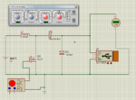
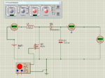
Here is another attachment with Schottky and results are same.
Capture.PNG
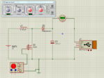
But here is problem. When I connect DC Ammeter in order to measure output current then it shows 0A.
Capture.PNG
Same with Input current.
Capture.PNG
Is this related with amplitude which I have set with signal generator i.e. 1V or I am gone dumb completely that I have forgotten the use of Ammeter :( ?

- - - Updated - - -

If I get success in it then I will design current limiting circuit. But I need your all help with this.
Thank you teachers :)
 

You forget to put some load. Try with some resistor.

Why you need current limiter, why to limit current, what is purpose of that ? At least for this design you will need a lots of current.


Best regards,
Peter

;-)

- - - Updated - - -

Yes of course simulator will work with or without schottky diode but with real part this can be big problem.

Simulators software is like this, but reality is something different :) :

**broken link removed**

https://lh5.googleusercontent.com/-OiR2Zahgryc/TWtD_hbzbWI/AAAAAAAABeY/S4F8ZLelA2w/s640/diy_flight_simulator.jpg
 
  • Like
Reactions: Eshal and FvM

    FvM

    Points: 2
    Helpful Answer Positive Rating

    Eshal

    Points: 2
    Helpful Answer Positive Rating
A current limiter to prevent excess current from flowing into battery ?????
Yes,you need to connect a load across to see if enough current is flowing.

Why don't you model a rechargeable battery in Proteus ????
I don't know if such a module is already available in Proteus,but you could do it in a blunt way by placing a large capacitor in series with a small resistor in series & the pair in parallel to a large resistor​
 

If I understand right, the boost converter is acting as an USB charger, providing a constant voltage. Battery charge is controlled by the connected device itself and is responsible for keeping safe battery conditions, current limit can be added to protect the boost converter against output overload. By nature of the boost converter, there's no short circuit protection without an additional fuse or switch.

Technically, current mode control of the boost converter would allow overload protection on the side.
 
@peter
Lol, I understand what does simulation mean. You are really a fun. Nice to meet you. :) And why I needs lots of current?

@rahdirs
Sorry, I didn't get your blunt way's statement. How to make a blunt rechargeable battery? pair of what? Proteus don't have model of rechargeable battery.
How much resistor should I place at output?
I have one thing in my mind. I didn't connect any load at the output that's why 0A current is shown at the output. But what could be the reason that Ammeter is also showing 0A at the input too???? Is it also related with output load? Means switch is ON and diode is ON so they have very low forward resistance may be this is the reason of 0A and that's why I need to connect load for input current too. Are you getting what I am talking about sir?

@FvM
But my application has low current requirement. So I think I don't need any overload protection. Do I?

@all experts
By the way, how much internal resistance of a battery has typically as I have provided the picture of my battery in post#16.
 

@peter
Lol, I understand what does simulation mean. You are really a fun. Nice to meet you. :) And why I needs lots of current?


If you have bad efficiency (very possible) your circuit will have needs to drain high current from battery/batteries to achieve 5V 500mA on output. Its not some mistique, just try this practical and you will get all answers what you need. Next step will be to make good 500KHz switcher which is in simulator added like simple "element" from toolbar.


@all experts
By the way, how much internal resistance of a battery has typically as I have provided the picture of my battery in post#16.


That battery as lots of others phone batteries in 800-1200mAh capacity range, can supply 1A-2A without problem. If your design have 50% efficiency on output for 500mA, you will need to supply or to drain from battery 1A. Next question is how much your battery will hold and what time you need, continuous or in intervals ?

For internal resistance do the test and measure. Resistance will change with charging, dicharging, healthy status,.... but this is one of good indicators of battery health status if you monitor that value from beginning of battery life.


With usage of two 1,5V alkaline batteries (mentioned in your post #16) to get 3V for power source at this higher currents, I think your design dont have too much chance for success.


I often use phone batteries for lots of projects with my voltage boosters, and I'm very satifyed. Sometimes I use 18650 Li-Ion batteries.


When you start to make this practical you will see lots of things.


https://www.youtube.com/watch?v=usRE3gLFnOc

https://hackaday.com/2012/12/12/lipo-internal-resistance-measurement-tool/


Best regards,
Peter

;-)
 
  • Like
Reactions: Eshal

    Eshal

    Points: 2
    Helpful Answer Positive Rating
@rahdirs
Sorry, I didn't get your blunt way's statement. How to make a blunt rechargeable battery? pair of what? Proteus don't have model of rechargeable battery.
How much resistor should I place at output?I have one thing in my mind. I didn't connect any load at the output that's why 0A current is shown at the output. But what could be the reason that Ammeter is also showing 0A at the input too???? Is it also related with output load? Means switch is ON and diode is ON so they have very low forward resistance may be this is the reason of 0A and that's why I need to connect load for input current too. Are you getting what I am talking about sir?

@all experts
By the way, how much internal resistance of a battery has typically as I have provided the picture of my battery in post#16.

A load for i/p current ????? Do you intend to connect a resistance at the i/p source.I don't think you need to do it,because if you connect a load at the o/p a current would flow from battery at the i/p.So there is no need to connect an additional resistor at the i/p or if you want to model to resistance of wires,i/p battery etc.... but you don't need to connect an additional resistance.

Try connecting 10.4 ohm first at the load & then vary resistance & observe the readings.

I searched on the net but i couldn't find data-sheet of your battery,but found one with similar characteristics:Li-ion Rechargeable Cell: 3.7V 1400mAh (5.18Wh) and in its specification sheet it was written its internal impedance to be around 90 milliohms at 25 degree celsius,although it may vary with charging, dicharging, healthy status,but you get an idea on how much its impedance generally is.....

Regardless of low current ppl try to include these in their design:
  • over-charge protection
  • over-discharge protection
  • Max current over-drain protection
  • Short circuit protection.


Lastly,i was saying if you can model a rechargeable battery in simulation.Refer to this:https://forum.allaboutcircuits.com/showthread.php?t=74776
 
  • Like
Reactions: Eshal

    Eshal

    Points: 2
    Helpful Answer Positive Rating
@peter
Sir, I agree with you. Bad efficiency can make my circuit to drain high current and I will not able to get the result for which I am working for.
My battery can last for 24hours if fully charged and condition is that I just use mobile for SMS not call or other multimedia.
One thing that confused me at this point. You said 500mA of current is much current to get from 3V (2x1.5v alkaline batteries). So do you think I should use a DC to DC current booster for this purpose or I have thought wrong? I will give it a practical try for real world. But I am also not sure if it works. Well see what result I get. I will let all you know.

@rahdirs
You have understood what I were talking about. Good to hear you.
Regardless of low current ppl try to include these in their design:

over-charge protection
over-discharge protection
Max current over-drain protection
Short circuit protection.
OK, I have gotten. I will try this one as I get my this design in working status.

@all experts
I will let you all know about my simulation result soon

Thank you

- - - Updated - - -

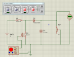
Can anyone tell me either it is boost converter or buck converter ? :(:cry:
Why my calculations are gone wrong?? :(
My boost converter has been turned into buck converter. Why???? :(
High input voltage and low output voltage. Everything is same as before.
output voltage.PNG
 

Your Open circuit voltage is 5.2 V,try with a larger resistance 100 ohm.
also attach ammeters in your circuit,both at i/p & o/p
 
  • Like
Reactions: Eshal

    Eshal

    Points: 2
    Helpful Answer Positive Rating
Open circuit voltage??? But we can find the value of R with Ohm's law. V=5.2V and I=500mA so R could be around 10Ohm. But this is not working though.
Here is with 100Ohm
1.PNG
Open circuit means with infinite resistance. Right?
Here is open circuit attachment
open.PNG

I will recalculate everything and try to construct circuit again.
 

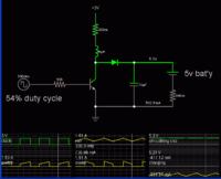
To provide comparison using another simulator

Here is a screenshot with scope traces showing how the boost converter will operate (approximately).

 
@FvM.
Sir, I thought it can drop 0.7V across it so providing 1V.
Here is my captured video. You can see how much frequency and amplitude I am providing to the switch.
Please tell me where did I go wrong.

@BradtheRad
Your circuit is working much good. You know, I tried your one and it is working well. But why not mine.

Thank you

- - - Updated - - -

Here is datasheet of Buz31 N-MOSFET.
It has VDS=200V. Is it OK to use?
 

Attachments

  • Boost converter problem.zip
    326.4 KB · Views: 97
  • BUZ31.pdf
    197.3 KB · Views: 91

Status
Not open for further replies.

Similar threads

Part and Inventory Search

Welcome to EDABoard.com

Sponsor

Back
Top