Continue to Site

Welcome to EDAboard.com

Welcome to our site! EDAboard.com is an international Electronics Discussion Forum focused on EDA software, circuits, schematics, books, theory, papers, asic, pld, 8051, DSP, Network, RF, Analog Design, PCB, Service Manuals... and a whole lot more! To participate you need to register. Registration is free. Click here to register now.

Audio Amplifier. Which class should I use?

Status
Not open for further replies.
sir D.C.=Ton/T

Here in the formula we have given Time periods in both numerator and denominator.

So how can I substitute voltage values?
 

Don't confuse ! as i told you at past you will select your desired ton ( of course you will control duty cycle for your desired values and i will tell you how you can do it ) . so , now it is the time for educate you more than past !
Consider we have this formula ( as i told at pas ) Vave= D.C*Vin =======> we need 10 volts from 250 volts ====> 10=D.C*250 =======> D.C=10/250 . it will be around 0.04 . ok ?
 
Hello sir..

Exactly I have found the same result as you did i.e. 0.04%

But then I was confused that either I should use D.C. formula or average formula.
 

Don't worry about it !
My internet is low speed too !
So , let me continue , as you can remember , we used a mosfet as switch . if we put 15 volts cross the GS junction it will be at maximum mode of conduction ( if we neglect VDS we can say it is short circuit ( DS ) ) . but in fact it is not a real short circuit . it will has a little value of series resistance , that called Rdson . did you know these things ?
 
very well . the dissipation for mosfet should be Rdson*ID^2 if it is turn on , all of the times . but in fact it is not on , all of the times . it is in at just ton . so we can take an average from dissipation :
1/T integral over Rdson*Id^2 dt from zero up to ton . ok ?
Read the datasheet of IRFP450 , and tell me the value of Rdson . then we can continue .
 
so can you calculate the dissipation across it's DS with D.C=0.04 ? consider frequency is just 50KHZ . vin is 250 volts and vout is 10 volts and RL is 1 ohms . ok ? show me the result .
 
Average of Ploss across DS:

Average=amplitude*D.C.
Average=320*0.5
Average=160W
There is a mistake here. Ploss should be less than 10W.
Thus the efficiency is better than you have calculated here:
efficiency = pout/(pout+ploss) *100
efficiency = 600/(600+160)*100
efficiency = 78.94%

I think the misunderstanding started here:
320W (approx.) is dissipated across MOSFET.

Can you do the simulation again for 20uS, and show the result for power across MOSFET?

-------------------------------------------------

Do you remember this calculation you did for the resistor?
248.3V across resistor.

I=4amp to 5amp (approx.) and V=248.3V
P=VI
P=(248.3)(5amp)
P=1241.5W
P=1.2KW
So voltage across resistor = 248.3V
Thus voltage across MOSFET = 250V - 248.3V = 1.7V
And power in MOSFET = 1.7V * 5A = 8.5W

-------------------------------------------------

Now, about the 300W that you found......

At the moment of switching, the voltage is between 0V and 248.3V

When the voltage across the resistor = 125V, then the voltage across the MOSFET is also 125V, and the current = 125V / 50R = 2.5A

Thus the power in the MOSFET = the power in the resistor = 125V * 2.5A = 312.5V at that moment.

However this is only for some nanoseconds, so it does not add much to the average power.
 
Last edited:
Hi godfreyl
I know where is the problem in simulation ! but i preferred to don't talk about it at this time ! . the problem is with driving way ! i know the efficiency should be better but because of high value of inrush current in gate ( it can be pretty large ) , the dissipation of GS junction added too . we will improve it , but i thought it is better that i don't talk about Ciss and it's effects at this time . ok ?
Best Regards
Goldsmith
 

@godfreyl

There is a mistake here. Ploss should be less than 10W.
Thus the efficiency is better than you have calculated here:

Sir how did you know that Ploss should be less than 10W? Is there any specific trick? or it is due to an experienced eye that you have? or You calculated result first and then tell me to correct it. How did you do that sir?

Can you do the simulation again for 20uS, and show the result for power across MOSFET?

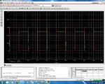
Yes sir, I have simulated it again (at 20us) for you and I have found result. See attachments, circuit named Analyzing MOSFET and its result named Analyzing MOSFET's result.

When the voltage across the resistor = 125V, then the voltage across the MOSFET is also 125V, and the current = 125V / 50R = 2.5A

Sir from where did this 125V come?
And how can be voltage across resistor and across MOSFET same?
voltage of VDS junction is said to be voltage across MOSFET but here you are saying voltage across resistor is 125V and MOSFET also has 125V. How? elaborate please.

Thus the power in the MOSFET = the power in the resistor = 125V * 2.5A = 312.5V at that moment.

How the dissipation at MOSFET and resistor be same?
And about what moment you are talking about here? elaborate please.

- - - Updated - - -

@goldsmith

Hi godfreyl
I know where is the problem in simulation ! but i preferred to don't talk about it at this time ! . the problem is with driving way ! i know the efficiency should be better but because of high value of inrush current in gate ( it can be pretty large ) , the dissipation of GS junction added too . we will improve it , but i thought it is better that i don't talk about Ciss and it's effects at this time . ok ?
Best Regards
Goldsmith

Sir I am not getting what you have said here?
What is ciss?
What is dissipation across GS junction? I have never heard about it and never calculated.
You are also talking about high value of inrush gate current. As much as I know, FET's have high input impedance therefore they don't have gate current. So what was your talking about.

- - - Updated - - -

@goldsmith

Sir you had given me a question here, (post#334)
so can you calculate the dissipation across it's DS with D.C=0.04 ? consider frequency is just 50KHZ . vin is 250 volts and vout is 10 volts and RL is 1 ohms . ok ? show me the result .

Here is how I solved it..

Ploss=(V^2)/(RL)
Ploss=(10^2)/(1)
Ploss=100W

Dissipation across its DS,
Average = amplitude * D.C.
Average = 100 * 0.04
Average = 4W
 

Attachments

  • Analyzing MOSFE's result.JPG
    Analyzing MOSFE's result.JPG
    303.4 KB · Views: 80
  • Analyzing MOSFET.JPG
    Analyzing MOSFET.JPG
    179.8 KB · Views: 83

Yes sir, I have simulated it again (at 20us) for you and I have found result. See attachments, circuit named Analyzing MOSFET and its result named Analyzing MOSFET's result.
Look at attachment named Analyzing MOSFET. It shows that Ploss = 8.473W.


Sir how did you know that Ploss should be less than 10W?
I explained that here:
Do you remember this calculation you did for the resistor?

So voltage across resistor = 248.3V
Thus voltage across MOSFET = 250V - 248.3V = 1.7V
And power in MOSFET = 1.7V * 5A = 8.5W

- - - Updated - - -

Sir from where did this 125V come?
And how can be voltage across resistor and across MOSFET same?
Supply voltage = 250V.
Thus voltage across resistor + voltage across MOSFET = 250V.

Thus....
  • When voltage across resistor = 0V, Voltage across MOSFET = 250V.
  • When voltage across resistor = 50V, Voltage across MOSFET = 200V.
  • When voltage across resistor = 100V, Voltage across MOSFET = 150V.
  • When voltage across resistor = 125V, Voltage across MOSFET = 125V.
  • When voltage across resistor = 150V, Voltage across MOSFET = 100V.
  • When voltage across resistor = 200V, Voltage across MOSFET = 50V.
 
Status
Not open for further replies.

Similar threads

Part and Inventory Search

Welcome to EDABoard.com

Sponsor

Back
Top