Continue to Site

Welcome to EDAboard.com

Welcome to our site! EDAboard.com is an international Electronics Discussion Forum focused on EDA software, circuits, schematics, books, theory, papers, asic, pld, 8051, DSP, Network, RF, Analog Design, PCB, Service Manuals... and a whole lot more! To participate you need to register. Registration is free. Click here to register now.

ATMEGA16/32 based single microcontroller inverter with battery charger

Status
Not open for further replies.
If you are going to start a new inverter,please note that your inverter should have a buzzer in it.
Buzzer and low bat led will on at 10.5v of battery till 10 volts.
At 10 volt stop oscillator at ics pins.
Or start buzzer and low bat led at 10.5v for one minute.
One minute is enough for computer user to save and exit from his programe.
In case of overloading toggle buzzer and over load led at 80% load.
 

Hi Tahmid,
Have you decided to witheld your support on my inverter project? you seems not to make any futher comment on it.

regards.
 

i am checking your schematic, it is better keep isolation between mains and circuit or no need to use opto-coupler for mains detect, why using two optocoupler for mains checking, and what the pin at 40 (PA0 ) doing ?(mains sense? better make isolate from mains)
i will look in more detail
 

Pin 40 is also,ADC0
i am checking your schematic, it is better keep isolation between mains and circuit or no need to use opto-coupler for mains detect, why using two optocoupler for mains checking, and what the pin at 40 (PA0 ) doing ?(mains sense? better make isolate from mains)
i will look in more detail
 

Hi Tahmid,
Have you decided to witheld your support on my inverter project? you seems not to make any futher comment on it.

regards.

That's not so. It's just that with exams knocking on the door, I'm so busy. I will try to keep helping you as I get time. I think you now need help on overload protection. In that regard, you first need to understand how to use a resistor as a shunt for current sensing to convert current to voltage using V=IR. For short-circuit protection, make use of the fact that during short-circuit, the voltage drops by a large amount and is very low.

Hope this helps.
Tahmid.

---------- Post added at 19:41 ---------- Previous post was at 19:39 ----------

@ rajudp,
Hi,
Pin40 is used for checking the mains voltage. It's not absolutely accurate, but does the work.

---------- Post added at 19:43 ---------- Previous post was at 19:41 ----------

@ everyone,
Hi,
I want a few suggestions as to what enhancements could be made if I make a brand new inverter with PIC. I've received a few suggestions:
1) Isolation between mains and circuitry
2) Use of buzzer

Can someone suggest more ideas and how to implement an isolated circuit without use of transformer?

Tahmid.

---------- Post added at 19:46 ---------- Previous post was at 19:43 ----------

For the PIC Inverter, I want to use 16F877A. I'll get to it when I get time.

---------- Post added at 19:47 ---------- Previous post was at 19:46 ----------

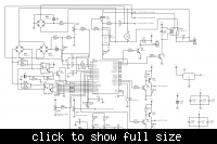
Here's the schematic as I drew it up:
 
  • Like
Reactions: moseba

    moseba

    Points: 2
    Helpful Answer Positive Rating
hi Tahmid,
thanks for your short tips. as for your new inverter design i would suggest
1----you move to PIC18FXXXX series because of their multiplication capabilities
2----try syncronous rectification(boost) charging algorithm , people on the forum might suggest to us how to implement this even if you dont have the capability to do it
3----i think sensing the voltage using OP AMPLIFIER LM324 with high input resistance could be a better option without the use of step down transformer

regards
 

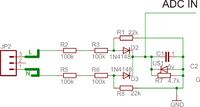
the isolation is a must for ups/inverter with external battery,
i will send you a circuit with resistor the output (signal part is almost like isolated )
 

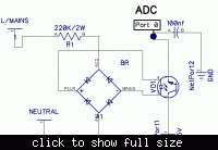
I think this is best idea rather than bridge rectifier(1n4007).
Although Tahmid used 330k/2w in his schematic and negtive of bridge(for mains,and out volt control) is conected with negtive of battery.
This schematic have less risk of electric shock at battery terminal than Tahmid,s schematic.
mains sensing
 

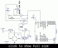
it is a working design

---------- Post added at 21:22 ---------- Previous post was at 21:22 ----------

only care about the mains part before resistors
 

Can we also use this type of schematic for feed back(output volt control in inverter mode)?
it is a working design

---------- Post added at 21:22 ---------- Previous post was at 21:22 ----------

only care about the mains part before resistors
 

for square wave it is not possible with .1uf capacitor

---------- Post added at 21:31 ---------- Previous post was at 21:30 ----------

if you increase the capacitor to more value ( your design uses 10uf ) it is possible
 

Here we almost use optocoupler(pc817)for isolation between mains and battery.
But have problem,when mains fail delay in chang over relay is more than 10 mil second.
for square wave it is not possible with .1uf capacitor

---------- Post added at 21:31 ---------- Previous post was at 21:30 ----------

if you increase the capacitor to more value ( your design uses 10uf ) it is possible


Hi,
Thanks for the schematic. Can you please explain the functioning of this circuit and why this poses less risk of hazard than my design?

Tahmid.

---------- Post added at 21:01 ---------- Previous post was at 20:59 ----------


Hi,
Thanks for the schematic. Is this for line sensing? I don't think this will help in line sensing as I can't measure the input voltage using this circuit.
 

in the circuit the negative(GND) or adc in ( both used internal circuit) not connected to live or neutral directly , if you swap the mains input also no difference in connection
 

YES FOR LINE SENSING AND IN WORKING.WHEN MAIN PRESENT,PC817 PROVIDE DC VOLTS AT 2 PIN(AN0) OF PIC 16F72.
THESE VOLTAGE CAN ADJUST WITH VR5K POT.(BELOW 5 VOLTS)
 
  • Like
Reactions: ali_01

    ali_01

    Points: 2
    Helpful Answer Positive Rating
Status
Not open for further replies.

Similar threads

Part and Inventory Search

Welcome to EDABoard.com

Sponsor

Back
Top