cupoftea
Advanced Member level 6

Hi,
We are trying to use TOPswitch HX and JX flyback control chips , but with transformers with NP/NS's
which mean that our design is not supported by their PI Expert Suite software.
Please help us to use TOPswitch's in such use case?
As such, we need to be able to calculate the gain and phase margin of our TOPswitch designs. However, we cannot do
this since TOPswitch modulator gains are the secret IP of Power Integrations.
And since the PI Expert Suite software cannot be used with our transformer's, we cannot assure stability
of our designs. This is bad because voltage mode converters offer additional problems with stability and so
must be done with a feedback loop calculation.
The TOPswitch is a voltage mode controlled chip (certainly when on or near max power).
Transient response testing is not sufficient to prove good stability margins with
voltage mode converters like TOPswitch….as the following article by Dr Ray Ridley discusses...
Transient response & Loop gains of power supplies (Dr Ray Ridley)
 drive.google.com
..with a current mode SMPS, you can get better gain and phase margins by simply lowering the loop
bandwidth.....but this is not so for voltage mode converters. As the above discusses.
So we then need to calculate the gain and phase margins. -But this isn't possible with TOPswitch, since
the modulator gains inside the TOPswitch are kept secret.
So in summary, for a voltage mode converter, one must calculate out the gain and phase margins....ie, you have to make out
the Bode Plots.....you dont necessarily have to do this with current mode converters......Dr Mike Engelhardt emphasis this in 1:55 to 2:30
of his video as follows...

 www.qorvo.com
...But how do we calc the Bode plots for a TOPswitch when Power integrations keeps the internal modulator gain a secret?
The modulator gain is needed to be known to calc out the Bode plot.
In the following communication, Power Integrations applications engineers actually state that the
feedback loop parameters of the TOPswitch internals are the secret IP of Power
Integrations and so are not divulged to the public. Therefore, without the modulator gain of the TOPswitch
we are simply unable to do the feedback loop calculation for the TOPswitch..

Page 47 of "power supply design, volume 1:control" by Dr Ridley states that for a voltage mode flyback.."The crossover frequency should be at least twice the resonant frequency".......by "resonant frequency" , Dr Ridley means resonance of Cout and L(sec). [or rather "LE", the effective secondary inductance since its flyback and not full or half bridge).
Also, Basso states that Voltage Mode Flyback crossover should be three times less than the RHPZ frequency (our designs go into
CCM at low mains and so RHPZ becomes an issue)
….the above two facts mean that there is only a narrow band of possibilities for the crossover frequency of a voltage mode flyback like TOpswitch. A little variance in the tolerance of the opto, or whatever, and the whole thing could go unstable. Not only that,
but TOPswitch designs often use a NPN in the feedback loop. NPN's have very poor tolerance, and so the chances of running into
stability at some point with a TOPswitch design is quite high.
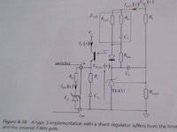
Page 25 of AN-47 shows the NPN being used in the topswitch feedback loop....
AN-47
Incidentally AN57 does not refer to TOPswitch HX or JX as the following tells....

Page 4 of AN57 by power integrations suggests that the LC resonant frequency of a TOPswitch flyback
should be greater than 500Hz...
AN57
This imposes a tight limit on the TOPswitch output capacitance, and throws into peril any output loading which may also feature an extra , large
electrolytic capacitor....instability may well then ensue.
Do you know what lies behind this recommendation of LC resonant frequency >500Hz?
Is it the fact that with TL431 based compensators that feature the "fast-lane/slow-lane" paths, the Type 3 compensator
is especially poor when LC resonance is >500Hz?
Here's a bit more on the TOPswitch Flyback output LC resonance frequency being >500Hz...
I mean, supposing your TOPswitch flyback suffers high variance in the opto CTR because you have five different parts as being "OK" in the BOM and need that flexibility to keep costs and lead times down....Or suppose the ESR (or the capacitance itself) of your output caps is highly variable.....or supposing some customers connect loads which comprise additional electro caps, thus dramatically increasing the output capacitance...etc etc.......current mode controllers can shrug this off and stay stable...a voltage mode converter may well go totally unstable under such changeable conditions.....
Like was sais, if the TOPswitch design is from the PIXIS design suite, or from the PI Expert software, then your good.....but if not......then surely one is in danger of instability?
We are trying to use TOPswitch HX and JX flyback control chips , but with transformers with NP/NS's
which mean that our design is not supported by their PI Expert Suite software.
Please help us to use TOPswitch's in such use case?
As such, we need to be able to calculate the gain and phase margin of our TOPswitch designs. However, we cannot do
this since TOPswitch modulator gains are the secret IP of Power Integrations.
And since the PI Expert Suite software cannot be used with our transformer's, we cannot assure stability
of our designs. This is bad because voltage mode converters offer additional problems with stability and so
must be done with a feedback loop calculation.
The TOPswitch is a voltage mode controlled chip (certainly when on or near max power).
Transient response testing is not sufficient to prove good stability margins with
voltage mode converters like TOPswitch….as the following article by Dr Ray Ridley discusses...
Transient response & Loop gains of power supplies (Dr Ray Ridley)
_17 Transient Response _STEP response n stability.pdf
 drive.google.com
..with a current mode SMPS, you can get better gain and phase margins by simply lowering the loop
bandwidth.....but this is not so for voltage mode converters. As the above discusses.
So we then need to calculate the gain and phase margins. -But this isn't possible with TOPswitch, since
the modulator gains inside the TOPswitch are kept secret.
So in summary, for a voltage mode converter, one must calculate out the gain and phase margins....ie, you have to make out
the Bode Plots.....you dont necessarily have to do this with current mode converters......Dr Mike Engelhardt emphasis this in 1:55 to 2:30
of his video as follows...

QuickStart Guide for QSPICE® Simulation Tool
This video provides a comprehensive introduction to QSPICE.
...But how do we calc the Bode plots for a TOPswitch when Power integrations keeps the internal modulator gain a secret?
The modulator gain is needed to be known to calc out the Bode plot.
In the following communication, Power Integrations applications engineers actually state that the
feedback loop parameters of the TOPswitch internals are the secret IP of Power
Integrations and so are not divulged to the public. Therefore, without the modulator gain of the TOPswitch
we are simply unable to do the feedback loop calculation for the TOPswitch..
Page 47 of "power supply design, volume 1:control" by Dr Ridley states that for a voltage mode flyback.."The crossover frequency should be at least twice the resonant frequency".......by "resonant frequency" , Dr Ridley means resonance of Cout and L(sec). [or rather "LE", the effective secondary inductance since its flyback and not full or half bridge).
Also, Basso states that Voltage Mode Flyback crossover should be three times less than the RHPZ frequency (our designs go into
CCM at low mains and so RHPZ becomes an issue)
….the above two facts mean that there is only a narrow band of possibilities for the crossover frequency of a voltage mode flyback like TOpswitch. A little variance in the tolerance of the opto, or whatever, and the whole thing could go unstable. Not only that,
but TOPswitch designs often use a NPN in the feedback loop. NPN's have very poor tolerance, and so the chances of running into
stability at some point with a TOPswitch design is quite high.
Page 25 of AN-47 shows the NPN being used in the topswitch feedback loop....
AN-47
Incidentally AN57 does not refer to TOPswitch HX or JX as the following tells....
Page 4 of AN57 by power integrations suggests that the LC resonant frequency of a TOPswitch flyback
should be greater than 500Hz...
AN57
This imposes a tight limit on the TOPswitch output capacitance, and throws into peril any output loading which may also feature an extra , large
electrolytic capacitor....instability may well then ensue.
Do you know what lies behind this recommendation of LC resonant frequency >500Hz?
Is it the fact that with TL431 based compensators that feature the "fast-lane/slow-lane" paths, the Type 3 compensator
is especially poor when LC resonance is >500Hz?
Here's a bit more on the TOPswitch Flyback output LC resonance frequency being >500Hz...
Voltage mode CCM flyback has limitations on output capacitance - Page 1
Voltage mode CCM flyback has limitations on output capacitance - Page 1
www.eevblog.com
I mean, supposing your TOPswitch flyback suffers high variance in the opto CTR because you have five different parts as being "OK" in the BOM and need that flexibility to keep costs and lead times down....Or suppose the ESR (or the capacitance itself) of your output caps is highly variable.....or supposing some customers connect loads which comprise additional electro caps, thus dramatically increasing the output capacitance...etc etc.......current mode controllers can shrug this off and stay stable...a voltage mode converter may well go totally unstable under such changeable conditions.....
Like was sais, if the TOPswitch design is from the PIXIS design suite, or from the PI Expert software, then your good.....but if not......then surely one is in danger of instability?
Last edited:
