Continue to Site

Welcome to EDAboard.com

Welcome to our site! EDAboard.com is an international Electronics Discussion Forum focused on EDA software, circuits, schematics, books, theory, papers, asic, pld, 8051, DSP, Network, RF, Analog Design, PCB, Service Manuals... and a whole lot more! To participate you need to register. Registration is free. Click here to register now.

74hc595 16f877a interfacing problems

Status
Not open for further replies.
Try this. Try the .hex file I have attached. Do not compile. Maybe your compiler is generating wring .hex file. I have compiled for 4 MHz external crystal. Post your exact hardware circuit.


Code C - [expand]
1
2
3
4
5
6
7
8
9
10
11
12
13
14
15
16
17
18
19
20
21
22
23
24
25
26
27
28
29
30
31
32
33
34
35
36
37
38
39
40
41
42
43
44
45
46
47
48
49
50
51
52
53
54
55
56
57
58
59
60
61
62
63
64
65
66
67
68
69
70
71
72
73
74
75
76
77
78
79
80
81
82
83
84
85
86
87
88
89
90
91
92
93
94
95
96
97
98
99
100
101
102
103
104
105
106
107
108
109
110
111
sbit SH_CP at RD0_bit;
sbit SH_CP_Direction at TRISD0_bit;
 
sbit ST_CP at RD2_bit;
sbit ST_CP_Direction at TRISD2_bit;
 
sbit DS at RD1_bit;
sbit DS_Direction at TRISD1_bit;
 
char uart_rd = 0, i = 0, j = 0;
char sequence[12] = {0b11000011, 0b11011011, 0b11100011,
                     0b11000011, 0b11111011, 0b11100011,
                     0b11000011, 0b11011011, 0b11100011,
                     0b11010011, 0b11011011, 0b11110011}; 
 
void interrupt() {
     if(RCIF_bit) {
           if(OERR_bit) {
                CREN_bit = 0;
                CREN_bit = 1;
                
                OERR_bit = 0;           
           }
           
           uart_rd = UART1_Read();
           
           RCIF_bit = 0;     
     }
}
 
void SPI_Send(char s) {
 
     char mask = 0x80;
     char i = 0;
     
     for(i = 0; i < 8; i++) {
           if(s & mask) 
               DS = 1;          
           else 
               DS = 0;
               
           SH_CP = 1;
           Delay_ms(2);
           SH_CP = 0;
           
           mask >>= 1;
     }
     
     ST_CP = 1;
     Delay_ms(2);
     ST_CP = 0;
}
 
void main() {
 
     TRISA = 0xC0;
     TRISB = 0x00;
     TRISC = 0x80;
     TRISD = 0x00;
     
     PORTA = 0x00;
     PORTB = 0x00;
     PORTC = 0x00;
     PORTD = 0x00;
     
     SH_CP_Direction = 0;    
     SH_CP = 0;     
 
     ST_CP_Direction = 0;    
     ST_CP = 0;
     
     DS_Direction = 0;
     DS = 0;    
     
     UART1_Init(9615);
     Delay_ms(200);
     UART1_Write_Text("Send a byte\r\n");
     UART1_Write_Text("-----------\r\n\r\n");
     
     RCIE_bit = 1;
     PEIE_bit = 1;;
     GIE_bit = 1;     
     
     while(1) {
                
           switch(uart_rd) {
           
                case '0':
                       i = 0;                   
                       break; 
                case '1':
                       i = 3;                      
                       break;
                case '2':
                       i = 6;                      
                       break; 
                case '3':
                       i = 9;                      
                       break;            
           };
           
           if(uart_rd) {           
               for(j = i; j = (i + 3); j++) {           
                     SPI_Send(sequence[i]);
                     Delay_ms(2000);          
               }
               
               uart_rd = 0;
           }
     }
}


Attachments

  • 74HC595 + LEDs + UART.rar
    37.8 KB · Views: 68
Last edited:
  • Like
Reactions: varunme

    varunme

    Points: 2
    Helpful Answer Positive Rating
mine is 20MHz crystal

Here is my schematic


First make a simple one using one 74HC595. Later you can cascade 3 HC595's and shift 24 bits into it. Try my circuit. In Proteus change to 20 MHz. Try attached .hex in hardware.
 

Attachments

  • PIC16F877A + 74HC595 + LEDs + UART 20 MHz Crystal.rar
    37.9 KB · Views: 69
  • Like
Reactions: varunme

    varunme

    Points: 2
    Helpful Answer Positive Rating
may be crystal frequency is the problem, i have 70 outputs, that will be possible using suitable number of 595s?
 

70 LED ? You need 9 HC595s. Post your exact hardware circuit. It should have crystal and its associated capacitors. My circuit connections are different. Only test in hardware.
 

seems to be some connection issue, some floating pins are there, when i touch the pins the leds on and off irregularly

yes 9 HC595

Ok, i will post it in sometime
 
Last edited:

Change


Code C - [expand]
1
UART1_Write_Text("Send a byte\r\n");


to


Code C - [expand]
1
UART1_Write_Text("Send 0 or 1 or 2 or 3\r\n");

 
  • Like
Reactions: varunme

    varunme

    Points: 2
    Helpful Answer Positive Rating
ok, I tried 0,1,2,3 only
 

Working project attached. I have tested it in Proteus and also hardware.


Edit

Tie SH_CP and ST_CP pins and you will see the display in a different way.
 

Attachments

  • PIC16F877A +74HC595 + LEDs + UART 20 MHz.rar
    80.8 KB · Views: 73
Last edited:

yes, its working, but the leds are floating and finalize in a stable state which differ in each reset
It works in your hardware properly?
 

Yes. it works fine in my hardware. Maybe some problem with your 74HC595.
 

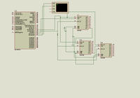
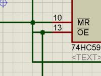
What are these wires meaned to connect?


You would also post the *.hex (and probably source) file if you want someone check the circuit's operation.
 

What are these wires meaned to connect?


You would also post the *.hex (and probably source) file if you want someone check the circuit's operation.

There is no overlap in MR OE, wire drag caused it, Hex file is the one uploaded by milan.rajik
 

Files attached.
 

Attachments

  • circuit.png
    circuit.png
    60.1 KB · Views: 82
  • PIC16F877A +74HC595 + LEDs + UART 20 MHz ver2.rar
    93 KB · Views: 74

In this code, the value is stable but all the 595 gets the same value

Code:
sbit SH_CP at RD0_bit;
sbit SH_CP_Direction at TRISD0_bit;

sbit ST_CP at RD2_bit;
sbit ST_CP_Direction at TRISD2_bit;

sbit DS at RD1_bit;
sbit DS_Direction at TRISD1_bit;

char i = 0, j = 0;

void SPI_Send(char s) {

     char mask = 0x32E3;
     char i = 0;
     
     for(i = 0; i < 16; i++) {
           if(s & mask) 
               DS = 1;          
           else 
               DS = 0;
               
          SH_CP = 1;
           Delay_ms(50);
           SH_CP = 0;
           
           mask >>= 1;
     }
     
     ST_CP = 1;
     Delay_ms(50);
     ST_CP = 0;
}

void main() {

     CMCON = 0x07;
     ADCON1 = 0x87;
     
     TRISA = 0xC0;
     TRISB = 0x00;
     TRISC = 0x80;
     TRISD = 0x00;
     
     PORTA = 0x00;
     PORTB = 0x00;
     PORTC = 0x00;
     PORTD = 0x00;
     
     SH_CP_Direction = 0;    
     SH_CP = 0;     

     ST_CP_Direction = 0;    
     ST_CP = 0;
     
     DS_Direction = 0;
     DS = 0;

              for(i = 0; i < 2; i++) {
                    SPI_Send(0x01);  }
                    Delay_ms(10);


}
 
Last edited:

I want to receive data from uart and send corresponding binary to led outputs which is stable
my application is to control solenoids, the solenoids makes english albhabets
so the data has to be stable to make those, I have altogather 70 solenoids, so the values in each 595 is different

that is if i send

11111000011110001110011, all the 595 has to show the whole value
but here all the 595 shows the same value
 

Then you should not tie SH_CP and ST_CP. Whenever there is new data to sent then clock 24 bits using SH_CP and then store this value to output by clocking ST_CP once at the end. Also 74HC595 will not be able to drive solenoids. You have to use ULN2803A between 74HC595s and Solenoids. What is the current rating of Solenoid ? If current rating is high then even ULN2803A can't handle and you need power transistors or power mosfets.

How you will send interger value through UART ? Do you have any sofware for sending data as integer (byte) and not as ascii value ? If yes, then I can write a code for you. It is just you have to receive 3 or 4 bytes as required through UART and store it in a long type variable and then clock this data to HC595 and store it.


First write a software which when you enter 24 characters like 110011.... it translates the 24 ascii characters ('1' and '0' s) to a 32 bit (4 byte) value and this can be sent as 4 bytes (integer value) through UART and PIC will read 4 bytes and send the bytes to 74HC595 else if you send 24 characters from PC to PIC then you will have to read 24 bytes and convert this to integer value.
 
Last edited:
  • Like
Reactions: varunme

    varunme

    Points: 2
    Helpful Answer Positive Rating
yes, i am using mosfets between 595 and solenoids, just for checking, I am using leds, solenoids is above 2803 range, 700mA

I have to send, all english alphabets, 0-9 through uart, just using hyperterminal
 

Status
Not open for further replies.

Similar threads

Part and Inventory Search

Welcome to EDABoard.com

Sponsor

Back
Top