Continue to Site

Welcome to EDAboard.com

Welcome to our site! EDAboard.com is an international Electronics Discussion Forum focused on EDA software, circuits, schematics, books, theory, papers, asic, pld, 8051, DSP, Network, RF, Analog Design, PCB, Service Manuals... and a whole lot more! To participate you need to register. Registration is free. Click here to register now.

600/800W 220~230v AC Inverter SMPS from 12v DC

Status
Not open for further replies.
Hi goldsmith, sam,
Your thread is going on very interesting, I am learning from you.
regards ani
 

you can use copper foil in place of copper wire , and as per design you can go upto 10A/Sqmm if the total length of wire is below 100cm

it is very difficult to solder many wires ( removing the insulation from coils ) there is one chemical for removing enamel from copper wire just dip the part to the chemical and wipe with a cloth then you can directly solder to wire
Could you please tell the name of the chemical?


goldsmith said:
And regarding your winding ! who told that you should solder your wires to that pin ? i have another solution ! when i have the same problem , i will remove that pin ! and then i will solder it directly ! it is up to you !
Yes, I can also do that. But my question is how this is handled in commercial products? I saw a transformer used in 500W inverter where the primary and secondary winding terminal is connected with the bobbin pins. Primary wire (or a set of multiple wires) is not so thick too! That's why I was asking which value of current density is being used commercially. Is is 10A/Sqmm within 100cm length?
 

Hi all,

I am following this discussion since a while now, and i must say it is very useful to me as well.
I currently build a DC-AC inverter 12V ~230V around 500W. I decided to use push-pull converter with UC2638 to boost the voltage.
Sam have you considered multilevel output stage, it has very low THD and losses.

Regards
 

Hi goldsmith, sam,
Your thread is going on very interesting, I am learning from you.
regards ani
Hi Ani
I'm so glad because it is useful for you .

Yes, I can also do that. But my question is how this is handled in commercial products?
Hi Sam
In commercial projects , most of the times , toroidal cores are using at high powers ( some toroidal cores in parallel together . ) but i saw some of them too with specific core plastic for winding ! with specific pins ( they have their ones ! ) and another way is using some cores in parallel and with wires with low gages thus there won't be any problem .
which value of current density is being used commercially
Density of current for each wire depends on frequency of operation . i think you saw my table ?
Good luck
Goldsmith
 

Hi Ani

Density of current for each wire depends on frequency of operation . i think you saw my table ?

Skin depth is dependent on operating frequency. When the frequency will be fixed, skin depth will be known. Using skin depth value we will be able to fix the maximum allowable diameter of a wire to be used here. Wire diameter must not be greater than 2*skin_depth.

Using current density value we'll be able to calculate the cross sectional area of a wire needed to allow the desired amount of current through it. Then the required number of wire can be calculated based on skin depth value. So, as per my understanding current density value is more important while calculating wire cross sectional area.
 

ter must not be greater than 2*skin_depth.
Why must not ? it can be greater than that , must not be lower than that ! when your wire gage is larger it is better ! ( more current handling )
as per my understanding current density value is more important while calculating wire cross sectional area.
Of course it is very important . and if you see my literatures about ferrite transformer and inductor design , carefully , you'll see i have attached a curve . J versus frequency .
All the best
Goldsmith
 

Hi rajudp,

Could you please tell the name of the chemical can be used for removing enamel?
 

Hi Goldsmith,

Could you please tell me how can I remove enamel from the wire easily? I've tried to generate Sinusoidal PWM in Matlab according to your notes. It seems okay to me. Could you please check the following plot and let me know whether it is okay?

sinosoidalPWM-matlab.png
 

I remove enamel from the wire easily
Hi Sam ! it is so easy ! i have two way ! 1- burning ! 2- using a cutter ! easily ! ( according to the Y axis thus your hand will be survived )
ABout your waveforms . and advise : a saw tooth , can be used in SMPS ! not for voice or link inverters . you should use just triangle wave . ok ?
Notice : amplitude of sine wave shouldn't be higher than triangle wave . it will be cause of high THD . ok ?
Why your square waves are such as that ? ( such as valley ?? ! why those are not smooth ? )
Good luck and best wishes
Goldsmith
 

Hi Sam ! it is so easy ! i have two way ! 1- burning ! 2- using a cutter ! easily ! ( according to the Y axis thus your hand will be survived )

Okay, both the processes are known to me. I'm waiting for the chemical name from rajudp.

goldsmith; said:
ABout your waveforms . and advise : a saw tooth , can be used in SMPS ! not for voice or link inverters . you should use just triangle wave . ok ?
Notice : amplitude of sine wave shouldn't be higher than triangle wave . it will be cause of high THD . ok ?
Actually, I didn't find any function to generate triangular wave in Matlab. Got sawtooth wave function which is just like as sin wave and square wave. Sawtooth is similar to triangular wave thats why I used that. Could you please suggest how can I generate triangular wave?
sinFx=.8*sin(2*pi*sinF*t);
sawFx=1*sawtooth(2*pi*sawF*t);

to keep the amplitude of sine wave below sawtooth, I used amplitude 1 for sawtooth and 0.8 for sine wave.

goldsmith; said:
Why your square waves are such as that ? ( such as valley ?? ! why those are not smooth ? )
Most probably it is due to low sample rate. Need to check...

- - - Updated - - -

Got better wave after increasing sampling rate. But how to generate triangular wave?
 

Hi Sam
Sorry i was a bit more than usual , busy !
Okay, both the processes are known to me. I'm waiting for the chemical name from rajudp.
Well i think you'd better to ask , a chemistry engineer about it .
Actually, I didn't find any function to generate triangular wave in Matlab. Got sawtooth wave function which is just like as sin wave and square wave. Sawtooth is similar to triangular wave thats why I used that. Could you please suggest how can I generate triangular wave?
sinFx=.8*sin(2*pi*sinF*t);
sawFx=1*sawtooth(2*pi*sawF*t);

to keep the amplitude of sine wave below sawtooth, I used amplitude 1 for sawtooth and 0.8 for sine wave.
I'm not using Matlab . hence i can't tell any thing about it .
( you can use Pspice , if you use Pspice , i can guide you more . perhaps other ones with experience in matlab can guide you , if you are just interested in matlab .
Got better wave after increasing sampling rate. But how to generate triangular wave?
In Pspice , i can tell you how , but not at matlab , because as i told i'm not using matlab .
Best Wishes
Goldsmith
 
Last edited:

I'm seeking attention of any Matlab expert in this topic.

Goldsmith,
I would use Pspice 5/6year back to solve some basic circuits. After that I've no communication with this software! Even I do not have the soft itself. :sad: But I can start using Pspice. Will it be hard to do the current experiment in Pspice? I'll download if there is nay free version.
 

But I can start using Pspice. Will it be hard to do the current experiment in Pspice?
Hi Sam
Of course if you just want see SPWM with your desired specifications , and research about it's spectrum , you can easily , do it with Pspice . try to do it , then if you couldn't i'll help you more .
Best Wishes
Goldsmith
 

hi,
i have gone through the post of this thread and i am working on a similar project. I want to ask whether the converter stage consisting of H bridge, HF transformer, rectifier and filter can be replaced with DC-DC boost converter. what are the pros and cons? please advice

thanks in advance
 

be replaced with DC-DC boost converter. what are the pros and cons? please advice
Hi Adeel
Boost converter may be used as first stage ( voltage multiplier stage ) however that is not a good idea .
Best Wishes
Goldsmith
 

hi,
i have gone through the post of this thread and i am working on a similar project. I want to ask whether the converter stage consisting of H bridge, HF transformer, rectifier and filter can be replaced with DC-DC boost converter. what are the pros and cons? please advice

thanks in advance

You should not be using a "boost converter". Here are some cons:
1) You do not get any isolation of the high voltage side from the low voltage side.
2) Peak current is too high.
3) Voltage stress across MOSFET is too high.
4) Losses will increase.
 

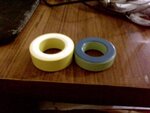
Please find the attached pictures of cores i am using to design inductor. Please advice about its specs, material. whether it can give incorrect reading with my LCR meter its inductance increases as current through it increases? and whether it is suitable for application with V=12V,Imax=8A, ton=190us and toff>=10us. if not suitable then which core should be used, advice about its physical appearence and other details. i am in doubt whether i am using the correct core for this application. color of core is green/blue ans yellow/white

thanks in advance
 

Attachments

  • IMG0177A.jpg
    IMG0177A.jpg
    16.9 KB · Views: 114

it is powder iron core,please visit the website, you can find these datasheet about core,www.micrometals.com,
I think you can use the core.https://obrazki.elektroda.pl/7992306500_1349353771.jpg

- - - Updated - - -

http://obrazki.elektroda.pl/6405091600_1349354075.jpg
Add the file, so that you can more know the core.

- - - Updated - - -

http://obrazki.elektroda.pl/7992306500_1349353771.jpg
 

i am using yellow/white core to design an inductor with L=300uh, i have wound 57 turns of 18 gauge wire and checked it with indutance meter to get the desired inductance. with 12V and for 190us, i should get a peak current of approx 7.7A, but when i constructed and used the inductance, it gives me only the peak current of 3.4A.

please advice why it is happening?

Thanks in advance
 

Status
Not open for further replies.

Similar threads

Part and Inventory Search

Welcome to EDABoard.com

Sponsor

Back
Top