Follow along with the video below to see how to install our site as a web app on your home screen.
Note: This feature may not be available in some browsers.

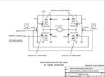
Just two MOSFET is used in the attached circuit as driver of high side MOSFET.Hi Tahmid
Are you sure about it ? because it's input gates are Cmos ( as i can remember ) . and a cmos gate won't accept TTL boundaries !

Welcome back goldsmith. Please let me know the problem and resolution. Also let me know the advantage of three level SPWM...goldsmith said:Hi sam
At last i came back again !
Your circuit will give you that waveform as well but it has a big problem . because you shouldn't expect advantages of a differential SPWM from that ! did you understand what i told you about driving the gates for this method really ? and do you know why i have mentioned that way ? do you know what is the big advantage of a three level SPWM method ? i think No .
Best Wishes
Goldsmith

Thanks for that !Welcome back goldsmith

Hi again sam
Thanks for that !
The main advantages of a three level SPWM are as below :
1-better efficiency
2-pretty low noise
3-pretty low THD
4- it won't need heavier filter sections .
And why these advantages are not available in your way ( your signal is like three level but in fact you shouldn't drive your mosfets with hat way ! because you will need differential action but here you won't have any differential action and of course the DC current through your filters will be higher !
you should create two SPWMs with messages out of phase together . thus the out put signal across the load before filtering will be as you want . and of course with main advantages that i have told you .
If you still can't get the point , i can write my meaning and the spectrum of SPWM in a paper and attach it here .
Best Wishes
Goldsmith


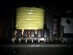
I took 35 pieces of 30cm 24SWG wire and bind with Teflon Tape to make a lit'z wire. While started for primary winding on ETD39 bobbin I observed that it had become vary hard to solder 35 no. of wires into the bobbin pins. How such thing is handled in practical transformer?
Another thing is the cross sectional area of the bobbin pins. I guess, cross sectional area of the bobbin pin will not be more than a 20-22 gauge of wire. How this pin will handle such large amount of current?
This is for a 300VA transformer using ETD39 core. But, as per my calculation ETD39 can handle around 500VA load. Cannot imagine what will be there in primary winding if it designed for 500VA. In this case, Ip=625/11=56.82. 24SWG wire needed = 58 no.
Could anybody please help me providing some practical examples how usually these things are taken care of?


Copper foil is not available here. Can I really use 10A/Sqmm in primary? Primary wire length is around 25cm. While making primary winding I thought this value current density (4A/Sqmm) is not used in practical implementation. If 10A/Sqmm is safe below 100cm length, I will use 14 wires (24swg) instead of 35. Could you please confirm whether this value (10A/Sqmm below 100cm) is used in transforms of our home appliances (SMPS, Inverter etc.)?you can use copper foil in place of copper wire , and as per design you can go upto 10A/Sqmm if the total length of wire is below 100cm
ETD39 can not handle with 500W if frequency is 100K, only handle with 300W.
Could you please let's know why you are thinking it can only handle 300w? As per the chart (https://www.edaboard.com/threads/229615/#post1100003 )shared by Goldsmith, ETD39 can handle 467w at 48kHz.Ferrite Core (ETD39) power handling capability calculation
J=400A/Sqcm
F=50KHz
Ac=1.23Sqcm
Aw=1.77Sqcm
P=0.707*J*F*Ac*Aw*B*1e-8
=0.707*400*50e3*1.25*1.77*1600*1e-8
=492.55w

Hi SamHi Goldsmith,
Thanks a lot for giving me such helpful tutorial. I was busy and could not concentrate this task for some personal reason.
In this model noises and harmonics become zero in the output. So, theoretically there should not need to use filter. I'm right? Hope I'll be able to generate such signal using MCU. Now, I'm trying to make transformer. I'm in a big trouble to make primary winding using 35 no of 24SWG wire. It is too hard to solder such huge number of wire with the bobbin pins.