Continue to Site

Welcome to EDAboard.com

Welcome to our site! EDAboard.com is an international Electronics Discussion Forum focused on EDA software, circuits, schematics, books, theory, papers, asic, pld, 8051, DSP, Network, RF, Analog Design, PCB, Service Manuals... and a whole lot more! To participate you need to register. Registration is free. Click here to register now.

27 MHz Amplification Query

Status
Not open for further replies.
Sir Dave, be aware that this is an OOK data transmitter, modulated with a ~350Hz square wave from a 555 timer, it doesn't need linearity.

RMMK, while I appreciate your desire to learn about RF transmitters, receivers and antennas, I think you are making life difficult for yourself by choosing 27MHz where antennas are still impractical to make unless you have lots of free space around you. It is true that as the frequency is increased, the construction techniques become more critical but up to about 1GHz is still fairly easy as long as you observe good practice. I suggest you move up to about 433.92MHz which is a license free frequency in most countries and half-wave antennas are only about 35cm across.

In one of my 433MHz units, I power the transmitter, a microcontroller and a temperature sensor from a 100x35mm solar panel, use a helical antenna about 30mm long and even with a power of only about 5mW I get reliable range of over 100m.

(Sir) Brian :lol:
 
  • Like
Reactions: RMMK

    RMMK

    Points: 2
    Helpful Answer Positive Rating
RMMK said:
Sir (again, i cant help it..... if i somehow loose this habit i will get a fine of around US$10- equivalent in my currency)

Oh WOW, OK you are forgiven and allowed to call Brian and I sir ;-)

Brian said:
be aware that this is an OOK data transmitter, modulated with a ~350Hz square wave from a 555 timer, it doesn't need linearity.

OK, no probs ... that would call for some reasonable LP Filtering then ... that last thing wanted would be to be producing masses of harmonics up the spectrum
and that wouldn't matter what freq the TX was on

Dave
 
Last edited:

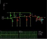
I did a simulation for the 433MHz transmitter RF Power amplifier circuit and the results are:
01.jpg

I observed that the results shown in the pic start to change after 600nsec. The values decreases; both the output voltage and power out. Why is it?
And it drops to a minimum as shown with around 100mW power output and after that it starts rising again:
01.jpg

Also I didnt use parallel LC arrangement because i was unable to tune it to exact 433MHz b/c in market no capacitor is available below 1pF and the lowest value of inductance obtained at 1pF is around 137nH which is also not available (120 and 150 are available!). also without tuning it and only using the inductors provide me better gain as per simulation.
Plz sir check the component values and also modify the design as you may deem fit of the above power amplifier for transmitter and the below pre-amplifier for receiver (uses BF998).......
01.jpg

Thanks!
 
Last edited:

I think its because of the time constant of the input circuit and the effect that you are over driving the input stage. Try running the simulator with an input signal of 1/10 of the existing. The 18 ohm resistor should be decoupled. I believe a useful increase in gain can be had by trying to match the collector circuits into the next base circuit. This can be done by tapping down the 2.2µH coil at say 20% and use this junction to feed the next base. It will allow the collector to operate into a higher impedance and so have more gain.
The output circuit is unreadable. Is it feeding 50Ω?, Dependent on how much current your PA transistor is drawing the its collector impedance could be any where between 120Ω (100mA) and 10Ω with 1A taken by the PA. So the output circuit should be designed for these impedances. In real life, a short pair of twisted insulated wires can be used as a tuning cap, or you can compress or extend a wound air spaced coil to to tune it.
Frank
 

Sorry for it being un-readable! I will upload a better version. Also I think there is a mistake in component values for the pre-amplifier of 433MHz (the last picture)..... I will upload the them for everything to be verified by the kind members before i actually build it :fight: !
Thanks
 

01.jpg
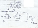
This was the pi-network at the output of the power amplifier stage...... The values i calculated seemed especially for inductors too low! There isnt any commercial made inductor of the specified value and the air core own made ones would be too long with very less no. of turns........... plz help!
 

CB and LB seem out of proportion to me. At 433MHz it would be unusual to have tuning coils in the uH region, see what happens if you reduce LB and increase CB to compensate. In a pi network you really only need a series capacitor to block DC, a series inductor and a capacitor at each end of it to ground. The name 'pi network' comes from looking like the letter Pi, two uprights (capacitors) and a flat top (inductor).

At these frequencies it is important to keep wiring length to minimum but you should be able to easily wind your own inductors from copper wire.

Brian.
 

Sir rather than working on a bandpass pi-network I have simulated a much simpler low pass pi network....... do u think its okay to go-ahead with this?
01.jpg

Sir I have observed that for a moment the Vce and Vbc goes to 25 and -45volts respectively and Vbe = -31Volts. Also for Q3 Ic was 6 Amps at max..... isnt it a bit too much?
Here is the export link file:-
https://tinyurl.com/qjoy52t

Sir if u have anything else in mind which i couldnt get; please scribble it out for me!
Thanks
 
Last edited:

You are wasting 0.5W by connecting the 300 Ohm load across the 12V supply. Try adding a series capacitor between the collector of the last transistor and the pi network so it blocks the DC.

Unfortunately with only my slow old laptop to work on, I can't really do much research at the moment but if I were to consider improvements, I would look at partially biasing the last two transistors and maybe experimenting with the inductance in their collectors.

Brian.
 
  • Like
Reactions: RMMK

    RMMK

    Points: 2
    Helpful Answer Positive Rating
Sir will it be okay to use Q1, Q2, Q3 as 2N2222A, 2N2219 and 2n3866 respectively in the conditions shown by the sim.:-
https://tinyurl.com/nbu9lcx

will they get burned out? :shock:

And here is the pre-amplifier stage for Receiver at 433MHz:-
01.jpg
Plz check if its okay......

Also sir what is the impedance of a whip antenna? I found certain equations as well as a calculator which solves them and provides its capacitance and a tuning inductor value but dont know what would be its impedance so that it may require to be matched with the circuit impedance..... here is that calculator:-
https://www.daycounter.com/Calculators/Whip-Antenna-Design-Calculator.phtml
 
Last edited:

The 2N2222 and 2N2219 are not really good enough at 433MHz, it would be easiest to use 2N3866 in all three positions. They wont burn out but their efficiency will be very low.

Regarding the preamplifier, it should work but you would get far better performance if the input circuit was tuned to the receiver frequency instead of being a low pass filter.

I think you are misunderstanding the differences between the L and C configurations. In instances where you want to peak at a particular frequency (parallalel LC) or reject it (series LC) you make them resonate at the desired frequency. If necessary you can adjust the output impedance with either a secondary winding in the coil (like a transformer) or by tapping into the coil part way along it's length.

In cases where you want to reject frequencies below (HPF) or above (LPF) a particular frequency you typically use pi networks or use one of the components in series and one to ground.

For your pre-amplifier the objective is to get as much gain as possible at only the frequency you want to receive so you boost the signal you want but not others. The best LC combination is therefore a parallel circuit across the input and maybe the output as well. I say maybe because you have to be careful if you use two tuned circuits with an amplifier between them because any magnetic coupling will turn it into an oscillator! This is why you often see screened 'compartments' in radio circuits.

For the transmitter output, you want some impedance matching to transfer maximum power to the antenna but also it should work as a LPF to supress harmonics at multiples of 433MHZ. The pi network is most suited for that purpose.

With my very poor computing facilities here at the moment I can't easily run simulations but if you can, try sweeping the input frequency across say 300MHz to 500MHZ and see if you can optimize the peak at 433MHZ. A well designed system will show a large peak at the frequency you want and a much lower peak at multiples of it.

Brian.
 

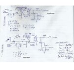
Sir from what you instructed that at the input of the receiver pre-amplifier; a parallel LC circuit is necessary. I have shown two schematics; one for 433MHz and the other one for 27Mhz. The 433Mhz one will employ a Yagi Antenna and the 27MHz antenna will use an inductor loaded whip antenna. Details are shown in the below schematic:-
Image (6).jpg
Is this okay sir or was there anything else you were asking me for?? :roll:
Also i want to ask for the impedance match.....

- - - Updated - - -

Here is the series of simulation results for transmitter Power Amplifier. Is this okay?
01.jpg02.jpg03.jpg
 

The receiver amplifiers looks OK. You might find it better to tap the antenna into the tuning coil, say 1/3 of the way from the ground side. This will help to prevent the antanna loading the 'Q' factor of the tuned circuit too much. To be honest, without knowing the exact technical details of the antenna, it's cable and connectors, it would be almost impossible to find the optimum connection point so some experimentation would be necessary. Tapping too close to ground will reduce the signal coupling but increase the Q of the tuned circuit, tapping too close to the top of the coil will reduce the Q but couple more voltage. The best place will be somewhere between the two. I suggest the tuning capacitor is made variable so you can adjust it for resonance, see if you can get 2-20pF variable capacitors for the 433MHz version and maybe 4-50pF for the 27MHz version.

For the simulations I meant to do a frequency sweep and plot the output versus frequency. I'm not sure if the simulator you used can do that and I do not have one to hand here to try it myself. What you should get is a fairly level line with a sudden peak at the frequency you want and nowhere else. The higher the peak and narrower it's edges are, the better the performance will be. You need to sweep from at least a few MHz below the signal frequency to at least twice it's frequency in a receiver simulation and for a transmitter simulation, from a few MHz below to ideally several times the frequency. It is normal to see one big peak at the frequency you want then smaller ones at multiples of it. The smaller the multiple levels are, the better the filtering is working.

Brian.
 

then should i go ahead with the building process now? :-D

- - - Updated - - -

Is it true that when a whip antenna is perfectly tuned; it behaves like a pure resistance tied to a ground?
But sir what is the resistance of a inductor loaded whip antenna? is it the radiation resistance? Plz explain this to me.........! I am thinking of using it on the 27Mhz setup.... I need this value to simulate the PA for 27MHz.... when I use 50ohm the performance gets pathetic with some 3-4Volts at output and with 300ohms its about 26Volts & 1.0Watt at output!

It may sound naive but is this a correct way to model an antenna as shown in the below pic! Something somewhere I dont think so but still........
01.png

The 10uH is actually the loading inductor for tuning the length wire to the 27Mhz frequency!
 
Last edited:

The output power is not the same as the output voltage! The power is the voltage squared divided by the impedance, at resonance that means 26*26/300 = 2.253W and 4*4/50 = 0.3W. Radiation resistance is not part of the power calculation, it is a measure of how much virtual resistance seems to be present in the path between the antenna and free space around it.

The question you ask about antenna matching impedances is difficult to answer, there are many factors to take into account so the formula isn't easy. Basically, the most signal will be available to receive when the output impedance of the amplifier is equal to the feeder impedance (cable connecting to the antenna) and the impedance of the antenna itself. The actual target impedance you choose is not important as long as everything is the same value, the reason for choosing standard values like 50 Ohms, 75 Ohms and 300 Ohms is these are standard values for commonly available feeder cables. 50 and 75 Ohms are common co-axial cable impedances and 300 Ohms is for balanced open wire 'ladder' feeders.

The loading coil should be in series with the antenna, not connected to ground. The idea is to fake the real length by adding a lumped inductance in series with the shortened wire part. The loading inductor does not radiate signal (maybe a little) but by making the transmitter think the antenna is better matched, it feeds more power to it and overall makes a stronger signal leave it. An antenna shorter than a wavelength long apears to be capacitive and adding an inductor makes it seem longer, similarly, if the antenna was too long it would seem to be inductive and instead of a loading inductor you would use a capacitor to make it seem shorter. When the correct balance is found, the antenna is neither inductive or capacitive and from the transmitters point of view it looks like a resistor. Although it isn't technically accurate, you could think of the loading inductor as being the missing length of antenna wire coiled up to save space!

Brian.
 

Oh! Sorry I read the output voltage in place of the output power....... my bad. I will use a low pass pi-network to match source impedance to the load impedance of 50ohms...... is it okay to presume that the inductor loaded 20-inches whip antenna will have impedance somewhere around 50ohms? Also Is there a way to physically check impedance?
There is another thing i want to ask is class C amplifiers are more efficient than the class A and class B due to its operation but why is it that when i check the DC input its about 3W = Pin and the output is just 1Watt?? Why is the efficiency this low sir (approx. 33%)?

Thanks
 
Last edited:

I built the preamplifier circuit for the receiver and the power amplifier for the transmitter and connected them to their respective ends on the 27Mhz version but i am not getting any signal reception! Previously without the additions it was providing 4-5meters of range and with the addition of power amplifier it got deteriorated. And when i connected the preamplifier on the receiver its receiving nothing! Plz help....... unlike in the past when i first built only the transmitter and receiver without the add-ons it was providing some signal reception when i place the the pairs too close but this time its not!
Also can you please tell me how to check if the BF998 is working or not??
 
Last edited:

Please post your schematics for the transmitter and receiver as they are at the moment. Its a while since you showed us and we need a refresh of information.

If you can, also measure voltages at each transistor pin in the receiver and in the transmitter do the same but under two conditions: 1. when everything is 'normal' and 2. with the base and emitter of the oscillator transistor linked together. The receiver voltages shouldn't significantly change so there is no point in measuring them twice but the transmitter voltages should change depending on whether the oscillator is running or not. The voltages should give some clues to the problem.

Testing the BF998 is difficult without special test equipment so for now I would assume it is good until proven otherwise.

Brian.
 

Yes a full circuit is required. Construct a diode probe and connect it to the junction of your transmitter and its aerial. If its working, you should see a small voltage (use your DVM on its lowest DC range). Once you have peaked this voltage, you are then sure that you are actually transmitting. In the past I have built 27 MHZ transmitters , crystal oscillator, buffer and PA stage and have lit low consumption bulbs (2V 50 mA) put in series with the aerial. Or if you monitor the current consumption of your PA stage it should change as the aerial tuning is changed, usually it will dip when on tune.
Frank
 

okay sir i will post the current schematics..... also i changed the BF998 with a fresh one but to no avail.....
 

Status
Not open for further replies.

Part and Inventory Search

Welcome to EDABoard.com

Sponsor

Back
Top