Follow along with the video below to see how to install our site as a web app on your home screen.
Note: This feature may not be available in some browsers.


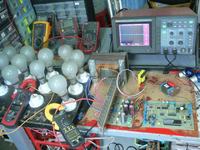
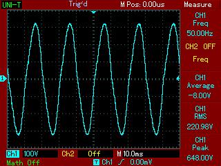
My design is a sine-wave stand-alone PWM voltage-source inverter (Not UPS)
with PIC16F876A MCU, with parameters: Uin=12V DC, Uo=230V AC, 50Hz, P=500W.
Inverter have an integrated input under/over voltage protection, output voltage regulation, output current protection and overtemperature protection.
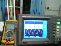
Output voltage is a pure sine-wave, generated with built-in PWM module of PIC MCU,
with frequency 20Khz.


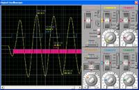
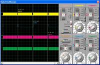
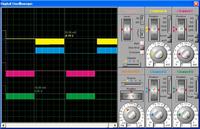
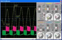
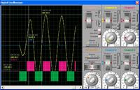
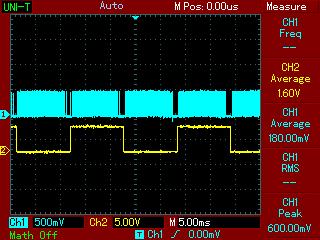
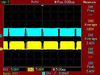
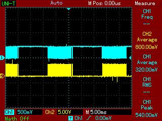



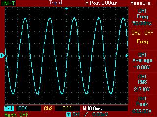
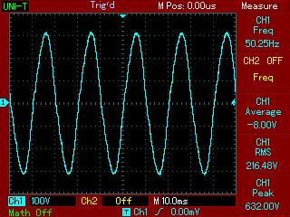
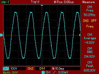
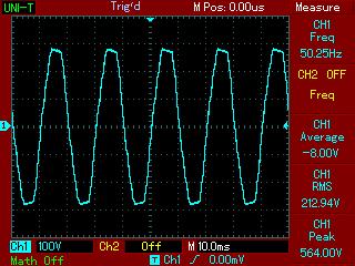


Californiajoe please mention hex file is for which device??? 16F876A or 16F877A???
---------- Post added at 04:05 PM ---------- Previous post was at 03:54 PM ----------
SN74HC257 is a data line selector
when A'/B= L it will give value from A at output (L or H), B is dont care
when A'/B= H it will give value from B at output (L or H), A is dont care
( G'= L to enable chip)
I think it should be more like PWM
---------- Post added at 04:09 PM ---------- Previous post was at 04:05 PM ----------
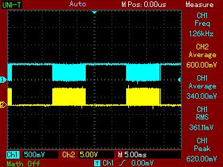
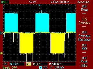
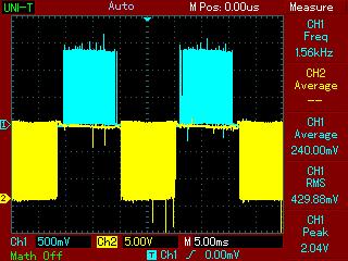
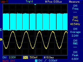
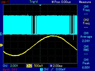
LM393 is a dual comparator, output should be PWM and PWM' at pin 1 and 7, check this on scope
---------- Post added at 04:11 PM ---------- Previous post was at 04:09 PM ----------
A'/B is a 50Hz sine wave signal
---------- Post added at 04:14 PM ---------- Previous post was at 04:11 PM ----------
ohh.... sorry.... A'/B is a square wave 50Hz, 50% duty cycle signal
Some time ago Taner told that this inverter works fine under 300 watts load, thuhtay can you please send me the PCB layout of the circuit, also will you please post the models of current and Voltage Transformers
Best Regards


Hi jami007
I think that A'/B signal is not 50Hz PWM signal in the C program source. It is only the directional signals 1 or 0 in order to alternate switching 20kHz PWM for 50 Hz half-cycle sine wave using SN74HC257D multiplexer. It is the command to generate the each driven PWM for positive half cycle and negative half cycle. I think the CCP2 PWM module is not used in this algorithm. It can see that the switching 20kHz PWM signals within 50Hz are generating sequentially using CCP1 PWM module with respect to the sine look up table 32- bits PWM duty cycle array. how do you think it is true?
---------- Post added at 22:18 ---------- Previous post was at 22:09 ----------
Hi jami007
I think that A'/B signal is not 50Hz PWM signal in the C program source. It is only the directional signals 1 or 0 in order to alternate switching 20kHz PWM for 50 Hz half-cycle sine wave using SN74HC257D multiplexer. It is the command to generate the each driven PWM for positive half cycle and negative half cycle. I think the CCP2 PWM module is not used in this algorithm. It can see that the switching 20kHz PWM signals within 50Hz are generating sequentially using CCP1 PWM module with respect to the sine look up table 32- bits PWM duty cycle array. how do you think it is true?
---------- Post added at 23:13 ---------- Previous post was at 22:18 ----------
Hi fri 'jami007'
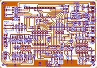
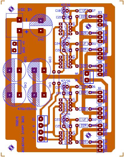
I posted my PCB design which is developed by using Circuit Maker 2000. Current transformer is constructed with reference (https://www.es.co.th/Schemetic/PDF/TZ2L9-TAEH.PDF). The Output Transformer rating is around 8Vac (Primary) to 250 Vac (secondary) E-I iron core low frequency transformer (50Hz).
Switching Controller PCB Design
H-Bridge Inverter PCB Design


Best regards


Nice design can you please share circuit maker 2000 design file
thanking you
Fragrance