Continue to Site

Welcome to EDAboard.com

Welcome to our site! EDAboard.com is an international Electronics Discussion Forum focused on EDA software, circuits, schematics, books, theory, papers, asic, pld, 8051, DSP, Network, RF, Analog Design, PCB, Service Manuals... and a whole lot more! To participate you need to register. Registration is free. Click here to register now.

[SOLVED] Pic 16f876a Pure Sinewave inverter

Status
Not open for further replies.
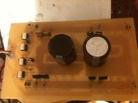
Hi, My PCB is drawn in track maker using circuit maker 2000 software. I will post again this PCB Softcopy.
 

Hello Thuhtay,
This is great news .
I shall like to have a copy of the same so that I can checkout the functioning .
Could you send this to my mailbox ID:: vimkha@email.com ....
thanks
 

Microchip - AN1279 - Offline UPS Reference Design Using the dsPIC® DSC

This application note can help.
 

can you share algorithm inverter sine wave with PIC16f8?? I dont know it. sory because I write english very bad!
 

dear taner. i have followed this thread and i think you have done a great job. thanks for your contributions. what i would like to ask you is that is it absolutely necessary to use ss34 diode for the high side driver. if not please specify possible replacements. best regards
 

Yes, it's tested and worked. But I have small problem with V out /see #653/. Also you can replace current sensing circuit with these:

Mr. Maharadga,

can you please tell me the type/model/value of the opto you used in this circuit.

much appreciation
 

Hello Thuhtay,
This is great project. Could you share source code file or file hex inverter sine wave for me. My mailbox ID:
Mod: No Private sharing. If you cannot download, there should be a reason for it. Or ask the author to upload on other file sharing servers.
 

Re: pic inverter

I am unable to download the PIC16 pure sine inverter schematic diag ,,PCB layout components &,track side along with the software data .
Could you kindly attach with mail at ID:: xxxxxxxxxxxxxx.In[/email] case the file is too big ,,kindly send software in a seperate attachment..
thanks
vimal
Mod: No Private sharing. If you cannot download, there should be a reason for it. Or ask the author to upload on other file sharing servers.
 

Re: pic inverter

please i need urgent help i did the design as noted by jamie007 but its not working at all :S im getting weird stuff
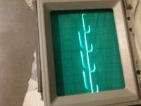
if i remove the lm324 ic the program starts blinking but the transistor blow NB: i'm testing without a transformer. i'll try to post an image of what i see before the transistors blow please reply as soon as possible . btw im using the no voltage regulation

---------- Post added at 22:39 ---------- Previous post was at 22:28 ----------

 
Last edited:

Well i checked ur inverter californiajoe and its the same as jamie's don't u both have the same software?
 

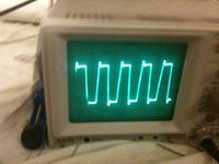
ok now i fixed the problem one or the tlp250 was missing a ground 8-O anyways now i have a bigger problem my output reaches 190v but the thing is i dont have a sinewave signal :S its kind of square what should i do ??? NB: thanx a lot guys for the effort .
ahhh i remembered one more thing if i use the voltage regulated software i have another problem the pic wont start
 

Well, you should start reading this thread from the first page. Many problemms are described many times. And yes, you have few diferent versios of software, but everything is already described, so step by step my friend. We all had to do the same. If you would use my PCB plan (as brain part and output part) the I would suggest you to use additional diodes to suply C23, C25 and C24, C26, as it is already done for C17, C19 and C18, C20. Additional diodes protects those capacitors against overheating.

Regards
 

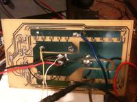
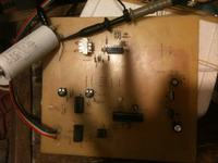
man thank for the help i rreally appreciate it . the thing is i've been reading the thread since a years ago :p a week ago i decided to build this invertor and now im facing these problems and btw i already did a pcb ill show u in the images. nevertheless i still can't find someone who has the same problem as i do my problem is that the output of the transfprmer is a square wave y is that . still one more thing does ur software work with jami's design ill post my schematic
 

Attachments

  • PIC16_Sine-wave_Inverter.pdf
    97.1 KB · Views: 630
As I can see, you have diferent PCB desighn, so I would suggest:
1.Check ones more every connection as by the scheme "PIC16_Sine-wave_Inverter.pdf"
2.Make sure that every component is 100% ok
3.Connect both transfomers in correct way, check signals with osciloscop (it is described at the begining of this thread and also later many times). Without correct connection inverter will not work at all.
4.Load software which is attached.

And this is pretty much all, it should work.

Regards
 

Attachments

  • sine_pwm_voltage-regulator_without_a-b_voltage_check.rar
    5 KB · Views: 481

I know im a pAin in the ass but i dix what u said i reversed the secondary of the trans an i got my sine wave but now i have another problem i have no regulation and ferther more when i try to increase the. Voltage using the gain resistor in the lm324 the voltage reaches 180v but the sig turn into a squarewave so back to original problem . Btw i uses the soft u gave me

Regards
 

Re: tz2l9

thanks for uploading the schematic , taner but i have some questions which i want to ask you . could you spare some time for me . my email id is umar4khan@gmail.com
please explain the method by which sine pwm is generated ..
 
Last edited:

Well, you have to find another foult in your connections. Check sine_pwm.doc to be sure everything is done as it should be.

Regards
 

Attachments

  • sine_pwm.doc
    29.8 KB · Views: 457

Status
Not open for further replies.

Part and Inventory Search

Welcome to EDABoard.com

Sponsor

Back
Top