Continue to Site

Welcome to EDAboard.com

Welcome to our site! EDAboard.com is an international Electronics Discussion Forum focused on EDA software, circuits, schematics, books, theory, papers, asic, pld, 8051, DSP, Network, RF, Analog Design, PCB, Service Manuals... and a whole lot more! To participate you need to register. Registration is free. Click here to register now.

What is load cell ? How it works ? thanks

Status
Not open for further replies.
The description clearly refers to an inductive transducer. Instead of the suggested LVDT design, it sounds more like center-tapped coil, that works in combination with a moving core and a differential inductance bridge.

would you like to elaborate it more ?

What would be the output of that inductive transducer that is going to the tension controller box to control the tension of the plastic packaging film ?

In this process ( plastic packaging film example ) , could you tell which one would be better to use inductive transducer or LVDT ?

thanks
 
With "center-tapped coil", I was referring to the initial post, that seems to desribe a three-terminal inductive sensor without an excitation coil. They are used in a bridge circuit, the behaviour is similar to a LVDT.

I don't see a point of better or not without detailed application specification. As far as I understand, your application doesn't require high accuracy, the sensor has been most likely selected for rugged design, lifetime, and last not least - availability.
 
All information collected together..........................
Inside it there are two small (tiny) transformers whose one wire is common to each other and there are two other wires (one for each).
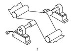
They are usually connected with a shaft (roller) that rotates and take the packaging film to the rewinding shaft.
there's just output cable having three wires coming out from the two transformers
Do You have some number on it? This no. is mentioned on it , BS 50K
they are two on each shaft (roller) one on the right side and other on the left side .......
HAN MI is the brand name of strain gauge which are present on both sides of the roller.
The machine is very old of its kind


The conclusion from previous.................................
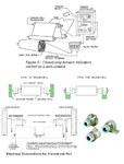
Web_Tension_Sensor_Problem.png

Like FvM wrote in previous post " three-terminal inductive sensor without an excitation coil."
I agree that .
another possible component is Strain Gage Transducer one half bridge per side.

For closer examination we need to know manufacturers and the exact types and models of devices.
Good pictures of components could possibly help.

General info about
**broken link removed**
 
Last edited:
All information collected together..........................
Inside it there are two small (tiny) transformers whose one wire is common to each other and there are two other wires (one for each).
They are usually connected with a shaft (roller) that rotates and take the packaging film to the rewinding shaft.
there's just output cable having three wires coming out from the two transformers
Do You have some number on it? This no. is mentioned on it , BS 50K
they are two on each shaft (roller) one on the right side and other on the left side .......
HAN MI is the brand name of strain gauge which are present on both sides of the roller.
The machine is very old of its kind


The conclusion from previous.................................
View attachment 63546

Like FvM wrote in previous post " three-terminal inductive sensor without an excitation coil."
I agree that .
another possible component is Strain Gage Transducer one half bridge per side.

For closer examination we need to know manufacturers and the exact types and models of devices.
Good pictures of components could possibly help.

General info about
**broken link removed**

thanks a lot though

How to test this " Web Tension Control: Under Pillow Block Tension Transducer " i.e. ( " Under Pillow Block Load Cells " ) ?

**broken link removed**
 
All information collected together..........................
Inside it there are two small (tiny) transformers whose one wire is common to each other and there are two other wires (one for each).
They are usually connected with a shaft (roller) that rotates and take the packaging film to the rewinding shaft.
there's just output cable having three wires coming out from the two transformers
Do You have some number on it? This no. is mentioned on it , BS 50K
they are two on each shaft (roller) one on the right side and other on the left side .......
HAN MI is the brand name of strain gauge which are present on both sides of the roller.
The machine is very old of its kind


The conclusion from previous.................................
View attachment 63546

Like FvM wrote in previous post " three-terminal inductive sensor without an excitation coil."
I agree that .
another possible component is Strain Gage Transducer one half bridge per side.

For closer examination we need to know manufacturers and the exact types and models of devices.
Good pictures of components could possibly help.

General info about
**broken link removed**

Bingo , you provide the very good link ......

now i got to know that these are " under pillow block load cells " that are connected on both sides of a roller (shaft) .......

now i want to test them ..... how to test them ? and when i removed its cover i found 2 small transformers inside it ...... whose one wire common to each and other 2, 2 wires are not common ......

thanks a lot
 

Still I am wondering what are those " 2 small transformers inside it" ????

You find everything here................

ULTRA SERIES UNDER PILLOW BLOCK TRANSDUCER
MODELS: UPB1 & UPB2
INSTRUCTION MANUAL

PAGE 16 : Figure 7 – Full Bridge Transducer Wiring
PAGE 17 : 4 TROUBLE SHOOTING

**broken link removed**

Another device...............
INSTRUCTION MANUAL
Model UPBH Tension Transducers

1.2 CONSTRUCTION AND MECHANICAL OPERATION
1.3 ELECTRICAL OPERATION
SECTION 5 TROUBLESHOOTING GUIDE

**broken link removed**

Look page 3. How the Measurement Signal Is Generated
**broken link removed**
 
Last edited:
Still I am wondering what are those " 2 small transformers inside it" ????

You find everything here................

ULTRA SERIES UNDER PILLOW BLOCK TRANSDUCER
MODELS: UPB1 & UPB2
INSTRUCTION MANUAL

PAGE 16 : Figure 7 – Full Bridge Transducer Wiring
PAGE 17 : 4 TROUBLE SHOOTING

**broken link removed**

Another device...............
INSTRUCTION MANUAL
Model UPBH Tension Transducers

1.2 CONSTRUCTION AND MECHANICAL OPERATION
1.3 ELECTRICAL OPERATION
SECTION 5 TROUBLESHOOTING GUIDE

**broken link removed**

Look page 3. How the Measurement Signal Is Generated
**broken link removed**

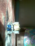
Here are the images of what i am talking about " 2 transformers are there with a core " ....

http://obrazki.elektroda.pl/88_1320156229.jpg
http://obrazki.elektroda.pl/61_1320156229.jpg
http://obrazki.elektroda.pl/12_1320156229.jpg
http://obrazki.elektroda.pl/57_1320156229.jpg
http://obrazki.elektroda.pl/25_1320156229.jpg


what is that then load cell or LVDT or strain gauge ?

thanks
 

Although incredibly blurry, the photos allow to conclude about an differential inductance sensor, as previously guessed.
 

Can not comment any on these blurry pictures.
 

Your pictures are taken with pinhole cam or ..........
But I can say NOT " load cell or LVDT or strain gauge ".
I vote for differential inductive sensor too.


All information collected together..........................
Inside it there are two small (tiny) transformers whose one wire is common to each other and there are two other wires (one for each).
They are usually connected with a shaft (roller) that rotates and take the packaging film to the rewinding shaft.
there's just output cable having three wires coming out from the two transformers
Do You have some number on it? This no. is mentioned on it , BS 50K
they are two on each shaft (roller) one on the right side and other on the left side .......
HAN MI is the brand name of strain gauge which are present on both sides of the roller.
The machine is very old of its kind


The conclusion from previous.................................
View attachment 63546

Like FvM wrote in previous post " three-terminal inductive sensor without an excitation coil."
I agree that .
another possible component is Strain Gage Transducer one half bridge per side.

For closer examination we need to know manufacturers and the exact types and models of devices.
Good pictures of components could possibly help.

General info about
**broken link removed**

how to test " under pillow block load cell " GTSA50M ?

**broken link removed**

thanks
 

As kak111 said 90% information is available in the datasheet of a components. Best always consult it first.
 
As kak111 said 90% information is available in the datasheet of a components. Best always consult it first.

can't you take any example ? or from the link that i have provided you ..........

thanks a lot though
 

It's not clear what you're presently asking for. The photos show the double coil of a kind of differential inductance sensor, but not the complete mechanics. It can be expected, that there's a moving part with two pole pieces placed above the both open side of the E cores.
 
Vari Ind.jpg
I can see and appreciate flowers in PERFECT FOCUS but not the Inductor. :-(
kak111 already gave you a lot of references, here is some for you, too.
http://www05.abb.com/global/scot/scot264.nsf/veritydisplay/7d590e52a4217e59c1257209003eef0a/$file/3bse030911r0201_-001.pdf
 
Last edited:
how to test " under pillow block load cell " GTSA50M ?
can't you take any example ? or from the link that i have provided you ..........

I show you : How to use datasheet and make test circuit ?

Your datasheet.............................
**broken link removed**

Look installation...........
Model GTS LoadCell_01.jpg

Measured force direction vertical downwards.

Look Schematic and electrical data.....................
Model GTS LoadCell_02.jpg

If measured with ohm-meter >> Gage Resistance: 350 ohm

Making test circuit....................

Excitation Voltage: 10 Vdc nominal
Output Signal: 21 mVdc nominal per load cell at full load rating

Cable Connector: PT01P-10-6P-SR; MAGPOWR mating cable assembly
part number SC15, or mating connector 12A36-1
(pin A, + power; pin B, + signal; pin C, -signal; pin D, -power)

That is all you need, now make circuit for testing................
Model GTS LoadCellTestSchema_01.jpg

Look force you need for test....................
Model GTS LoadCell_03.jpg

You find out GTSA50M >> 50 kg = full load >> then Output Signal: 21 mVdc nominal

So when vertical force down is 50 kp then meter should read 21 mV
25 kp >> 10.5mV ; 12.5 kp >> 5.25mV .... etc.

And everything found on datasheet, i think : it was not so hard.

Regards KAK
 
Last edited:
Status
Not open for further replies.

Part and Inventory Search

Welcome to EDABoard.com

Sponsor

Back
Top