Continue to Site

Welcome to EDAboard.com

Welcome to our site! EDAboard.com is an international Electronics Discussion Forum focused on EDA software, circuits, schematics, books, theory, papers, asic, pld, 8051, DSP, Network, RF, Analog Design, PCB, Service Manuals... and a whole lot more! To participate you need to register. Registration is free. Click here to register now.

Variable frequency sinusoidal wave oscillator

Status
Not open for further replies.
Again hi my friends
Hi
I tried to change the frequency of that triangle wave , but i need a little help here . is it possible that you guide me for that, please?
Best Regards
Goldsmith
 

Hi dear all
I didn't get my answer , yet. is here anybody that can help me , please ? each idea is welcome .
Thanks
Goldsmith
 

This link has several sinewave generators. I believe it's a different list from another link I posted in this thread.

The writer thinks the most useful one is the phase-shift type using 3 op amps. Its frequency can be tuned with a dual-ganged pot. (6.5 - Phase-Shift + Distortion Cancellation)

**broken link removed**
 
Dear BradtheRad
Thank you for your very good reply , really , it contains very good things that i have been looking for .
Do you have any good idea for a variable frequency triangular wave ? i know i can use an square wave generator and then use an integrator with gang of capacitors and a selector , but i thought perhaps you have a better idea .
Many thanks for your kindness .
Best Regards
Goldsmith

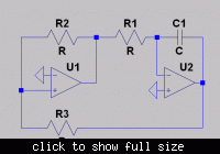
I remember a circuit I have seen some weeks/months ago. It was based on the classical relaxation oscillator principle - however, the passive RC element determining the time constant was replaced by an active integrator.
This circuit provides two outputs: (1) squarewave at the "switching" opamp and (2) triangular wave at the integrator output.
Perhaps this design fits to your needs?
 
Dear LvW
Hi
Thank you very much for your reply .
Is it possible that you give me it's diagram , please ? it seems very interesting for me .
Thank you very much
Best Regards
Goldsmith
 

I guess, the integrator + comparator with hysteresis triangle oscillator has been mentioned a hundred times at edaboard. It's also the operation principle of the FG1617 function generator. There are only implementation differences for the integrator and comparator. I thought, this had been obvious.


You can make a frequency variable oscillator by varying R1 and placing a sine-shape network behind the triangle output.
 
Last edited:
Dear FvM
Hi Oh i didn't think that "LvW" is referring to that circuit , i thought perhaps it is another thing because he mentioned that he saw this circuit some mounts ago . but if you are referring to the circuit with comparator and op amp to achieve an square wave and triangular wave ( and integrator and a hysteresis mode amp ) i have tried it for many times , but when i increased the frequency the out put wave ( triangular out put ) was alike with everything , unless a triangle ! . i have used some high frequency opamps and comparators , e.g LM311 , and LM318 and LM338 . Perhaps i had some errors in design ?
And about the FG1617 , some mounts a go , when i started this thread you suggested me that good function generator , and helped me in some of the sections of that , but at frequency changer section i stuck . is it possible that you guide me , more about it , please ?
Thank you
Best Regards
Goldsmith
 

Of course I don't know which circuit LvW means, but his description applies exactly to the shown (and most likely well-known) circuit.

Saying the FG1617 has the same operation principle abstracts from various details, e.g. independently variable rise and fall times. Also the high frequency limit has been considered by a different (open loop) integrator design. Finally, it has been designed with economic components about 30 years ago.
 
Generally speaking: According to specification, available components designing creativity.

New designs are mostly using digital signal processing and DACs.
 
I think at the start pages of this thread i mentioned that what are my reasons that i want design it with maximum analog circuits . i will design a completely digital one , after this , but , as for this , i want use just analog components e.g the generator that you introduced .
Thanks
 

Of course I don't know which circuit LvW means, but his description applies exactly to the shown (and most likely well-known) circuit.
........

Yes, that`s the circuit I was referring to, which was discussed in this forum some time ago. (By the way: ...."to the shown circuit" ? Where is it?)
There are some alternatives possible dependend on the applied integration principle (inverting, non-inverting).
As mentioned by Goldsmith for smaller time constants (higher designed frequencies) the circuit looses its triangle capability.
It is interesting to note that this is one of the rare oscillation circuits that exhibit a smooth transition from non-sinusoidal (square, triangle) to sinusoidal oscillation - just by tuning a resistor ratio.
 
Dear LvW
It is interesting to note that this is one of the rare oscillation circuits that exhibit a smooth transition from non-sinusoidal (square, triangle) to sinusoidal oscillation - just by tuning a resistor ratio.
Thank you for your reply . can you tell me more about this , please ?
Thank you
Best Regards
Goldsmith
 

Dear LvW and Dear FvM
Hi
is it possible that you guide me , please to select a good way to achieve it , please ? i have an idea but it has a little problem , is it possible that you tell me your idea about it and how can i improve it , please ?
The idea : for square wave : use an schmitt trigger not gate , and an RC network and then another not to improve the wave shape . thus if i use a potentiometer i think i can change the frequency as well . but i don't know that why when i did it , the out put duty cycle wasn't 50 percent , exactly .
Thank you very much
Best Regards
Goldsmith
 

As FvM et al have shown, the variable integrator best suits your need.

(As an aside, there are many digital synth solutions including DAC wave shaper converters (linear DAC on output of n-bit up & down counter gives triangle wave, at input freq /n. A standard up or down counter gives sawtooth with freq/n output. A since FM modulated software clock generates a sinusoidal up/down counts give a sinewave output.. random up down counts gives random signal. Any arbitrary signal can be generated using approximation at n x freq and integrate with up-down counters in h/w or s/w with DAC output DAC or analog output) You can even use logarithmic µLaw or A-Law 8 bit DACs for > 70dB dynamic range. The digital approach is useful if you need more resolution than say the PWM obvious method using double precision.) now back to the simple solution.... :cool:

Theory of Operation
If you vary the speed of integration with a log pot such that its output reaches a threshold and then inverts direction of integration, you get a constant amplitude triangle wave and square wave. Sine is shaped form Triangle by log function using diode compression.

Although interesting but irrelevant, recall that a triangle and a square wave have the same Fourier magnitudes except inverted phase of harmonics. The integrator shifts the phase in the time domain by 90deg for V vs I and also shifts the polarity of harmonics in the frequency domain. from -1,1,-1,1.. to 1,-1,1,-1... ( my memory is fuzzy.. but I think that is right)

A Sine can be approximated by performing a log conversion of the peak signals of the triangle wave to shape them, as the sine and triangle have the same slope or dominant fundamental component.

For extra points you can empirically show how log of integral of square wave relates to fundamental in frequency domain.

I refer to the popular design....and leave for you to work out the values. Any 50 ohm variable gain driver can be your output. A DC level shifter is useful with a large bipolar supply.
Screen shot 2012-06-02 at 10.03.41 AM.PNG
 
Last edited:
Dear SunnySkyguy
Hi
Thank you very much for your reply and good suggestions .
And the circuit that you have attached seems pretty good . but how much will be the maximum frequency that i can take from it ?because it is based on relaxation method too , and i tested the same one, after some frequencies , ( above 100 KHZ ) the triangle wave was nearby sine wave ! although the circuit that i'm referring to just had triangle and square t. is your circuit optimized ? ( i think it is optimized and i can get high frequencies from it . am i right ? if you tell me a bit more explanations about it , i'll be happy and grateful .
Thank you for your help .
Best Regards
Goldsmith
 

YOu must remember that a triangle is the fundamental plus many harmonics, just like the square wave.
Next you must realize what Gain-Bandwidth product means.
If you have 100kHz with say 7 harmonics ; 100, 300, 500, 700, 900, 1100, 1300, 1500 then you need 1500 kHz bandwidth.
That means if you want any gain, Av, you need Av * BW product. so choose your Op Amp and gain wisely. Don't ask until you have tried to find the best combination then report back.
Obviously you need rotary switches for Cap to change range as well and don't expect more than 3 decades in one range, then you can have as many decades as practical.. getting down to low frequencies requires special low leakage polyurethane caps. eg. < 10Hz for best performance....

- - - Updated - - -

YOu must remember that a triangle is the fundamental plus many harmonics, just like the square wave.
Next you must realize what Gain-Bandwidth product means.
If you have 100kHz with say 7 harmonics ; 100, 300, 500, 700, 900, 1100, 1300, 1500 then you need 1500 kHz bandwidth.
That means if you want any gain, Av, you need Av * BW product. so choose your Op Amp and gain wisely. Don't ask until you have tried to find the best combination then report back.
Obviously you need rotary switches for Cap to change range as well and don't expect more than 3 decades in one range, then you can have as many decades as practical.. getting down to low frequencies requires special low leakage polyurethane caps. eg. < 10Hz for best performance....
 
Status
Not open for further replies.

Part and Inventory Search

Welcome to EDABoard.com

Sponsor

Back
Top