Continue to Site

Welcome to EDAboard.com

Welcome to our site! EDAboard.com is an international Electronics Discussion Forum focused on EDA software, circuits, schematics, books, theory, papers, asic, pld, 8051, DSP, Network, RF, Analog Design, PCB, Service Manuals... and a whole lot more! To participate you need to register. Registration is free. Click here to register now.

Variable frequency sinusoidal wave oscillator

Status
Not open for further replies.
Dear FvM
I designed this programmable current source ( for half cycle) . how can i use it as an integrator?
View attachment 66940
Regards
Goldsmith

Your circuit is a follower, not a current source. It won't do much of anything useful.

Start at the beginning. What do you actually want? The first step in any project is clearly defining your goals. That's a critical part of engineering. Sine only or sine/square/triangle? You want something that is somewhat round on top (5 or 10% distortion) or an actual sine wave? How much distortion? 1%, .01%, .0001% ? You appear to want an analog-only design, not digital or hybrid. And, you don't want to use an IC that already does this pretty well, like an XR2206. Why? What realistically do you need for total frequency range? How many ranges are acceptable within that total range. Voltage controlled or variable resistor/capacitor controlled or digital or frequency-controlled? What output voltage into what load resistance? How much variation in output versus frequency and load are acceptable? How much do you want it to cost? Ar you limiting the design to use parts you already have or or can you use a wider range of parts? Every choice you make can drive the design in a different direction.

If you have already decided you want a rough high-distortion sine-looking sort of wave with a diode wave shaper, it's best to start with a design that actually works. There was a design posted already for a triangle generator that was not too bad. A little old and complicated, but possible. Build it first and understand how it works. Modify it to suit your needs. If you want a cheaper simpler design, you can use a 555 timer with a current source and sink. There are circuits on the web. Look them up. Then make a diode wave shaper. Then make an output buffer. On the other hand, if you want something better then define your needs first. Building a lot of things and then trying to see if they fit your needs is a good way to build a lot of things and have nothing that is useful. Start at the beginning. End at the end. Starting in the middle is a good way to spend a lot of time on nothing. If your goal is simply to build and try examples of many different ways to solve the problem, make a list of the different basic approaches and research a circuit for each. Start with a published circuit that works. Understand why they made the choices they made and then try another. Only half the job of engineering is solving the problem. At least half the job is understanding the problem.
 
For such a high frequency span I would use some integrated DDS generator chip. Like ISL5314 or AD9850. Or maybe some higher level one which incorporates a PLL? I've built a circuit which could generate frequencies anywhere from 1Hz (software limited, probably would go much lower) to 10MHz. My circuit was following:

Sine wave was generated by ISL5314 clocked at 125MHz. This chip has current output designed for use with 50R load which was what I've used. Output voltage across load resistor spans from 2 to 3V. Output from DDS was filtered by 9-th order Butterworth LC pi-type filter. This voltage was buffered and shifted using LM7372 opamp in inverting configuration. Offset was adjusted with MCP4822 dac arranged as 16-bit. The signal was then being fed to LMH6505 variable gain amplifier (or rather attenuator in this particular case)which was adjusted in the same was as offset voltage. Output was then fed to Lm7171 opamp in non-inverting configuration which had fixed gain of 30 which enabled +/-10V swing. The end stage was LM7372 as voltage follower (buffer) because of it's high current capability.

This setup could produce quite clean sine at 10MHz as well as at 1Hz. If not going for such a low frequencies to be covered RC or LC high-pass filter could be used instead of level shifter.


My opinion: unless you are going for 100MHz+ frequencies the DDS chips are the way to achieve widely variable frequency sine wave
 
Dear Mr Hoffman
Hi
Thank you for your helpful guidance .
about the programmable current circuit : i think by changing the voltage of non inverting of op amp , the voltage of gate of the jfet , will change , and the current of jfet is depends on it's gate source , voltage , thus the current of load can't exceed from the current gain . with this definition , i said that , that circuit is current source . but is your mean , that this behavior is not the procedure of a current source ? if yes , why?

And about the function generator that i want design :
The tolerance of that : it is better , for me , that , be about normal . because it is not the governments project!!!!:-D
And i want to design it with analog systems , because , i want to learn it's basic . and analog systems are beautiful in my idea.( for me ) . and i can learn about some new circuits with them.
And i want the frequency from 1 HZ ( least ) up to 2 MHZ- or until 10MHZ .
And about it's cost , i want that it's cost be about the money of a student , for example up to 200 $.(I'm not rich man !!!)

And about it's wave forms : i just want sine and triangular and square , waves and the variable duty cycle for the square wave.
and about the frequency changing: i want use variable resistor / capacitor selection for that.
and about the out put voltage and current : i need +- 15 volt at out put. and for the out put stage and impedance , i think a simple HF complementary pair ( class AB ) can help here .
those are my goals.
And thank you for your helpful advices so i will start at the beginning because by this way i can learn good .
Best Regards
Goldsmith


Your Life is your message to the world. Make it Inspiring.
Lorrin L Lee
 

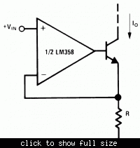
I designed this programmable current source
It doesn't work as a current source as shown because it misses a current sense resistor and feedback path. Maybe the structure wasn't quite clear in the original schematic. The circuit principle is shown below for a negative current source, with a BJT instead of a FET. As a minor disadvantage, there's a small error introduced by the base current.

 
Dear FvM
Thank you for your reply.
but the behavior of both of them was alike with together when i simulated both of them. but the circuit that you attached at top . is better i think , because it can compensate the DC bias of be of transistors. is it right?
you said that this is for negative current . but i think it is for positive currents . because the NPN transistor can not give the negative current. is it right?
and i think for simultaneous current i should make , twin circuit with negative and positive current . but how can i use this circuit as an integrator? my mean is that , where is the input of square wave ? i know , that if the current of a capacitor be linear , it will work as a linear device , and it can take a linear integral . but how can i use this circuit as an integrator?
Thanks for your help.
Respectfully
Goldsmith

---------- Post added at 23:11 ---------- Previous post was at 22:45 ----------

Oh sorry , yes my last circuit was wrong. know i can understand that where was the problem .
But how can i use the second circuit as an integrator?
 

I didn't want to discuss everything at once. You should get an idea of the current source concept first. You should have noticed that it's basically a current regulator which senses the output current at sense resistor connected to the emitter. A positive current source would use a PNP BJT or P-FET, a sense resistor connected to positive supply and also a control voltage referenced to positive supply. Details like OP input voltage range have to considered, too.

As the previously shown FG1617 schematic shows, to create an integrator, the current source(s) are feed to to a capacitor, and it's voltage is buffered by a voltage follower. Furthermore, one or both current sources need to be switched to perform alternately charge and discharge of the capacitor.

Robert has recently suggested to go for a straightforward generator design, e.g. using a XR2206 chip. poorchava suggested DDS. I support both ideas and think they are appropriate, if you primarly want to build a generator. If you want to learn about basic building blocks of analog electronics, designing a triangle generator from the scratch makes sense. But you'll need patience to study the circuit concepts thorougly, possibly make some simulations or even better assemble test circuits to get familiar with them and make the first steps to become an analog electronic designer.
 
Dear FvM
I confused by the circuit of FG1617 . because , i couldn't find , the place of input of square wave , in that. is it possible , that you simplify it , please?
And thank you for your advice .
Sincerely
Goldsmith
 

What do you mean with input of square wave? As previously explained, it's a self oscillating triangle oscillator, similar to a two OP integrator + comparator with hysteresis circuit.
 

And about the function generator that i want design :
The tolerance of that : it is better , for me , that , be about normal . because it is not the governments project!!!!:-D
And i want to design it with analog systems , because , i want to learn it's basic . and analog systems are beautiful in my idea.( for me ) . and i can learn about some new circuits with them.
And i want the frequency from 1 HZ ( least ) up to 2 MHZ- or until 10MHZ .
And about it's cost , i want that it's cost be about the money of a student , for example up to 200 $.(I'm not rich man !!!)

And about it's wave forms : i just want sine and triangular and square , waves and the variable duty cycle for the square wave.
and about the frequency changing: i want use variable resistor / capacitor selection for that.
and about the out put voltage and current : i need +- 15 volt at out put. and for the out put stage and impedance , i think a simple HF complementary pair ( class AB ) can help here .
those are my goals.
And thank you for your helpful advices so i will start at the beginning because by this way i can learn good .
Best Regards
Goldsmith


Your Life is your message to the world. Make it Inspiring.
Lorrin L Lee

This makes it more clear. Your budget is more than enough to make something quite good. You want a full function generator. But, there's no such thing as a "normal" tolerance. Commercial function generators can be anywhere from a few percent distortion down to extremely low distortion. You can use a high distortion generator to do general testing. You would use a very low distortion signal generator for high-quality audio circuits. I have units with 0.0001% distortion for audio testing. I have some with 3% distortion for general use. Square and triangle waves are much easier to generate than good sine waves. If your budget is $200 or less, assume that the cost of the electronic parts must be about half and the cost of a case, power supply, knobs, switches and mechanical parts are the other half. You can use cheaper parts for the case and controls but you'll have something that looks cheap and may not be reliable. You could get a pretty decent piece of used equipment for less than $200. You'll pay the same to build it yourself and may not have something quite as nice, but if you want to build one give it a try.

There are 3 ways to proceed. A good sine generator which you then use to generate a square wave and then make a triangle wave from that. A triangle generator which you use to make a square wave and and also feed into a sine shaper to get the sine wave, or two different circuits - a good sine generator along with a good triangle/square generator. The best you can do with a sine shaper is 1 or 2 percent distortion and that is not easy. I wouldn't do that. If you start with a sine wave and then make it into a square wave and a triangle wave, it is hard to make a symmetry control for variable duty cycle and hard to keep the triangle wave at a fixed amplitude. If you make both a good sine oscillator and a separate square/triangle generator you get everything. Sine, square, triangle, ramp, pulse and distortion probably around 0.1% without a huge lot of work. 0.01% is not too hard over most of the range. 0.001% or better is possible but harder. That's how I would do it. You can use a multi-gang pot or connect several variable resistors together with gears to have everything work with one knob, or you can do that electronically. I expect you can do this with about a dozen integrated circuits and don't need any really expensive or hard-to-get parts. They're all normal-sized parts that you can solder easily.

I would start with the sine generator part. I do the hardest part first. There are two basic kinds of high-quality analog sine circuits. Wien Bridge and State Variable. Several ways to do each one and they all have good and bad points. They both have a core circuit, a feedback control circuit and a way to adjust the frequency. The frequency control requires two simultaneous adjustments. The state-variable can do that with control if you use OTA amps but they're not great and the distortion won't be as good. Read about them both, make a list of the good and bad things and pick one approach to try. That's the first step. I won't tell you which one I would use. Pick one and say why you picked it.
 
I think, the approach as given by Robert H. is a very good one and, certainly, will help Goldsmith to find the final design.
However, I feel that one short comment is appropriate:

Quote: There are two basic kinds of high-quality analog sine circuits. Wien Bridge and State Variable

Yes, it's true that the mentioned oscillator topologies (WIEN, integrator based) can be regarded as "basic" alternatives.
However, they suffer from the requirement that frequency variation requires parallel tuning of two components (to keep the oscillation condition unchanged).
I like to point to the fact that there are alternatives - of the same signal quality or even better - with single-element tuning capabilities, for example
based on an active bandpass stage. As another advantage, the element to be tuned is grounded (FET control possible).
 
Also true but I've never done a bandpass design I liked. Wien bridge can be tuned with a single element. Not over 10000:1 or constant amplitude but you level that out in the AGC. Really just wanted show there isn't one answer to his original question. There are lots of answers and there's a process for finding an answer you can tolerate. First you need a proper question.
 

Yes, that's the normal - however, difficult and time-consuming - task of an engineer to select the appropriate circuit (out of several alternatives).
And "appropriate" means: The best trade-off between performance, cost, parts count, power consumption, flexibility (tunability), .....
By the way: Another single-element controlled harmonic oscillator is a circuit based on passive tank configuration and active L realization.
 

Dear Mr Hoffman
Again Hi
I thought about things that you said . and i analyzed the ways and i thought about their advantages and disadvantages . and i selected this way:
I want use a pure sine wave generator ( wien bridge with AGC and twin potentiometer as frequency changer device ) . and square / triangle wave generator (and with electronically variable network.) . and with 0.1 percent THD ratio .
So what is your idea about my choice ?
With Appreciate
Goldsmith
 

.... wien bridge with AGC and twin potentiometer as frequency changer device .........

...and don't forget adapting (switching) of the AGC time constant for different frequency ranges.
 
Dear FvM
Hi
Is it possible that you say , that how , that circuit works as an independent triangular oscillator ,please?
Best Regards
Goldsmith

---------- Post added at 16:42 ---------- Previous post was at 16:40 ----------

Dear LvW
Again Hi
Is it possible , that you describe , that how can i adapt that for many ranges of frequencies , please? should i use some R and C ?
With Appreciate
Goldsmith
 

Is it possible , that you describe , that how can i adapt that for many ranges of frequencies , please? should i use some R and C ?
With Appreciate
Goldsmith

As an alternative to a real AGC (FET based) you could consider a diode-based amplitude control.
In this case, the frequency tuning certainly would be easier (no adaption of the AGC time constat) - depending on the required tuning range.
However, as a disadvatage, I doubt that a THD of 0.1% can be achieved.
Perhaps somebody else can report on some related experiences?
 
But how this circuit change the input wave to a sine wave? with the capacitors of diodes (internal)?

It's the reduced resistance in the diodes as the waveform approaches peak. Near the peak the diode is just reaching full on. The result is to cause the triangle wave to be rounded, resembling a sine wave.

I think by changing the frequency , the out put amplitude of my integrator will change . when i changed the frequency and then the out put shape changed , but i changed the gain of my integrator , thus again the out put wave was a sine wave at good shape .
How can i improve this problem? your suggested circuit is very good if i can improve it .

You need a triangle wave generator whose amplitude doesn't change.

How do you make one? Many square wave generators have a triangle wave going on somewhere. Usually on a capacitor. With the 555 timer the capacitor charges and discharges inside a range between 1/3 and 2/3 of supply voltage. The waveform is a triangle.

This can be run through a buffer and/or level shifter. If you're lucky it will maintain a stable amplitude through a wide range of frequencies.
 
Dear Mr Hoffman
Again Hi
... I want use a pure sine wave generator ( wien bridge with AGC and twin potentiometer as frequency changer device ) . and square / triangle wave generator (and with electronically variable network.) . and with 0.1 percent THD ratio . So what is your idea about my choice ?
Goldsmith

I think that's a good approach. Use the things that work well from different techniques to make something that satisfies all your needs. You need a fairly good sine wave for audio work and a diode shaper won't do that. You need a variable-symmetry square wave/pulse for a lot of testing and the bridge oscillators won't do that easily. So, you make a unit with both bridge and triangle generators to get everything.

If you start with a square wave and integrate to get a triangle, the amplitude changes with frequency unless you vary the time constant at the same time. Too complicated. If you integrate a current until a fixed voltage is reached, all you need to change is the current. Simpler. A triangle wave is simply made with a current source and capacitor. You source current into the cap to make the rising part of the triangle, you sink current from the cap to make the negative slope. If the source and sink currents are equal, you have a symmetrical triangle. If they're unequal, you get a ramp with different rise and fall times. That's a useful feature. The basic idea is switch on the source current until the triangle reaches a fixed maximum (say +1 volt), then switch on the sink current until the triangle goes down to -1 volt. You need two variable current sources, one source and one sink. You need two comparators (one for the positive limit and one for the negative). You need a latch to remember whether the triangle is rising or falling, and you need a capacitor. You want the current source and sink to be equal to each other for a triangle. They need to be different to make a ramp. Start with a pair of voltage-to-current sources so you can either make them the same or have the sum be constant if you want variable symmetry without changing the frequency. Start reading about current mirrors. That's how you do the current source and sink. An opamp compares your input voltage with the voltage across the emitter resistor of a transistor. The collector current then changes with your input voltage. That will sink a current to ground but not source. Connect the transistor collector to a current mirror. That changes the sink current into a source current. The current sources don't change quickly. Any opamp will work plus a few transistors and resistors and diodes. The current sources have to switch on and off. You do that with a transistor. A simple latch (74HC00) gets set and reset by your limit comparators. LM393 will work to begin with. Won't work well at 10 MHz but will be OK at 1 MHz. The latch gets set and reset by the comparators. The latch tells which current source to turn on and off. You then have a constant-amplitude triangle wave on the integrating capacitor. The frequency is controlled by the voltage going into your voltage-to-current mirrors. You can get probably 100-to-1 range with each integrating capacitor. You'll need to switch several capacitors for several ranges. 1 to 100 Hz, 100 to 10K, 10K to 1 MHz and a smaller one for above 1MHz. They'll probably be around 1 uF, 10 nF, 100 pF and maybe 10 pF on the high range. Low ranges will be linear. Highest will not.

Start reading. You won't be an engineer in a week.
 
Dear Mr Hoffman
Again Hi
Thank you for your help.
What is your idea about this: after making the triangle , wave , giving that to the comparator , that wants to do comparing between variable DC voltage , and so it's out put will be variable duty cycle square wave ?
Is that right? and if yes , what is your idea about that?
Appreciate
Goldsmith
 

Dear FvM
Hi
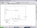
Thank you for your help. is your mean by the triangle wave oscillator , some thing like below figure?
Triangle.JPG

triangle2.JPG
But what should i do for negative cycle?
Thanks in advance
Goldsmith
 
Last edited:

Status
Not open for further replies.

Similar threads

Part and Inventory Search

Welcome to EDABoard.com

Sponsor

Back
Top