Continue to Site

Welcome to EDAboard.com

Welcome to our site! EDAboard.com is an international Electronics Discussion Forum focused on EDA software, circuits, schematics, books, theory, papers, asic, pld, 8051, DSP, Network, RF, Analog Design, PCB, Service Manuals... and a whole lot more! To participate you need to register. Registration is free. Click here to register now.

Transformer Inductance

Status
Not open for further replies.
BUt will I be able to apply a voltage bigger than the rated one in the primary (so the core can saturate) without burning the transformer?

You can increase the primary voltage for few seconds till the waveform get distorted.
 

A series resistor in the primary of a transformer will give incorrect measurement of saturation voltage. The resistance value adds to the impedance of transformer and hence reduced current flow, you have to apply more voltage for core saturation. So you can’t find the accurate saturation voltage.
For 230V/18V transformer. We can directly probe to secondary terminals. What happing in the primary side during saturation will reflect in the secondary also.
This will give no load saturation voltage. We have to connect the rated secondary load for measuring the actual saturation voltage.

I said to use a "suitable" resistor. That means, among other things, to use a value small enough that the added voltage drop is negligible compared to the drop across the winding. Even better would be to use a current probe clamped around one lead of the primary.

Probing the secondary winding will not show what's happening with the primary current. Examining the primary current for increasing deviation from sinusoidal is what is being done.

I should mention to gabi_pds--you must use a technique that is safe if you attempt to measure the voltage across a current sense resistor in series with the primary winding. Either use an oscilloscope with isolated inputs, or a differential isolated probe, or a current probe, or a 1 to 1 isolation transformer to provide an isolated 230 volts to drive your test transformer.

No secondary load should be applied for this measurement.

- - - Updated - - -

- distorted magnetizing current due to nonlinear core characteristics. The third harmonic has a magnitude of about 20% of fundamental in this case.

Although the waveform looks like "far from sinusoidal" (post #13), the effect on the total RMS current is quite low (about 2%), so a determination of current phase angle by magnitude measurements (post #12) still works quite good.


So what tell the measurements about significance of real input current?


You can view at it from two sides. Phase angle of impedance is about 74 degree. You can see it as a significant loss term (cos φ ≈ 0.27), or as nearly pure reactant current (sin φ ≈ 0.96).

You said in post #12, "If the series resistance voltage drop is large enough". Connecting a large enough resistor in series means that the transformer winding is no longer being excited by a voltage source. The effect of saturation in generating current peaks will be reduced. Anyway, the whole notion of "impedance" assumes sinusoidal currents and voltages. Yes, this method can give some kind of approximation, but why bother; the OP has a scope. Just look at zero crossings of current and voltage and get an approximation that way, without adding a disturbing resistance in series.

I don't know how much equipment the OP has, but another good technique (to determine if the exciting current is mostly reactive) is to measure the true core loss with a wattmeter, and the apparent power (with no secondary load, of course) with ordinary ammeter and voltmeter. If the true power is significantly less than the apparent power, that means that the exciting current is mostly reactive, and an inductance calculation based on applied voltage divided by exciting current is a good approximation.

In the absence of a wattmeter, the math capability of a modern digital oscilloscope can be used to multiply the voltage and current waveforms and thereby obtain the true power consumption. Nowadays, this is what I do, because I'm also examining the current waveform anyway to note the amount of peaking due to saturation of the core.

Whether of not it's a significant loss term would matter if we were concerned with transformer efficiency (losses), but this thread is about determining winding inductance. The fact that the winding current is nearly a pure reactive current is what we care about in this thread, so the second viewpoint is the relevant one.

- - - Updated - - -

The OP is now asking about saturation.

gabi_pds, saturation is a non-linear phenomenon, and its onset in regular transformer iron is gradual.

Remembering Faraday's law, the flux in the core is proportional to the integral of the applied voltage. If we could find a way to produce a signal proportional to the flux in the core, we could use an oscilloscope in X-Y mode to display the B-H characteristic of a core.

The way to do this is to make a integrator from a resistor-capacitor series connection. If we apply a voltage across the series combination of a resistor and capacitor, the voltage across the capacitor alone will be the integral of the voltage across the series combination, IF the time constant of the series combination is long in comparison to the 50/60 Hz applied voltage.

This youtube video shows the technique:

https://www.youtube.com/watch?v=91WVF3P1c6E

I used a 33k ohm and 3 uF capacitor for my integrator, and displayed the hysteresis loop of a small power transformer:

attachment.php


You can see that the onset of saturation is gradual. There are other magnetic materials that have a very sudden onset of saturation. These materials are often called "square loop" material. Here is the hysteresis loop of such a core material; these materials are never used for an ordinary small power transformer because they are more expensive than regular transformer steel:

attachment.php


So you can see that the question of when saturation occurs in regular transformer cores is a matter of judgement; you have to define the point of saturation to suit yourself. If the core were made of the square loop material, the occurrence of saturation would be more precisely determined.
 

Attachments

  • TEK0143.BMP
    12.4 KB · Views: 213
  • TEK0145.BMP
    12.4 KB · Views: 194

So if use a resistor and a capacitor with these same values (because the frequency of the applied voltage is 50 Hz), should I observe the B-H characteristic of the core? Do I need to plot the voltage in the capacitor versus the current flowing through it?
 

Capacitor voltage versus transformer current.

Some digital oscilloscopes have integral among their math functions, they can display a flux equivalent voltage integral without the RC circuit.
 

Capacitor voltage versus transformer current.

Some digital oscilloscopes have integral among their math functions, they can display a flux equivalent voltage integral without the RC circuit.

I have often wished that I could use the digital scope built-in integral function for this purpose, but it has been my experience that the output of math functions can't be one of the inputs to the scope's X-Y mode; they are only useable in Y-T mode.

I don't want to say that no scope can use a math output in X-Y mode. I think the very expensive Rohde & Schwarz series RTO scopes can do this, but my Tektronix TPS2024 can't, nor can the Agilent DS50X4 scopes.
 

I have used integ() function in XY-mode with LeCroy Waverunner (not the most recent model). I realized that it doesn't work e.g. on Agilent MSO6104, which has fixed assignment of channel 1 and 2 in XY-mode.
 

- distorted magnetizing current due to nonlinear core characteristics. The third harmonic has a magnitude of about 20% of fundamental in this case.

Although the waveform looks like "far from sinusoidal" (post #13), the effect on the total RMS current is quite low (about 2%), so a determination of current phase angle by magnitude measurements (post #12) still works quite good.


So what tell the measurements about significance of real input current?


You can view at it from two sides. Phase angle of impedance is about 74 degree. You can see it as a significant loss term (cos φ ≈ 0.27), or as nearly pure reactant current (sin φ ≈ 0.96).

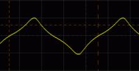
You are in Germany, but the text in the image is Polish. Apparently this isn't an oscilloscope capture that you made yourself.

This image is doesn't look quite correct for the magnetizing current of a real transformer winding which is energized by a sine wave. Since the flux in the core is proportional to the integral of the applied voltage, the flux peak occurs at the end of each half cycle, not at the peak of the applied sine.

The exciting current consists of a sine wave of current due to the resistance of the wire, plus a peaky waveform with the peak occurring near the end of each half cycle. The image you show is too symmetrical to be representative of a small real transformer. It's what you might expect from some sort of an ideal winding with no resistance.

Very small transformers in particular tend to be designed to operate further into saturation than larger ones, because their regulation is poorer, and their surface area to volume ratio is more favorable to dissipate heat; this gives an exciting current waveform that is even more peaky than larger transformers.

I found a small (5 VA rating) transformer to make some measurements with.

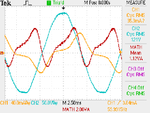
Here's a scope capture of the applied voltage (blue), exciting current (orange) and the instantaneous product of the two (red):

attachment.php


The average of the red waveform is the true power dissipation (1.12 watts). The exciting current is much more peaky than shown in the image you posted. The third harmonic is 37% of the fundamental.

The apparent power is the product of the applied voltage (121 VAC) and the exciting current (35.3 mA), which is 4.27 VA, 3.8 times the true power. The apparent power is sufficiently larger than the true power to justify characterizing the exciting current as a mostly reactive current.

From this we get the primary inductance as 121/(2*Pi*60*.0353) = 9.09 henries. Compare this to the inductance measured on an LCR meter:

Code:
Applied         Inductance
Voltage

.01                  3.02H
0.1                  3.29H
1.0                  4.56H
 10                  8.30H
 

Attachments

  • TEK0140.png
    TEK0140.png
    12.9 KB · Views: 229

You are in Germany, but the text in the image is Polish. Apparently this isn't an oscilloscope capture that you made yourself.
You're jumping into conclusions. It's just the Edaboard preview text... (And it's a real measurement)

The reason why the waveform is slightly different has been previously discussed. But generally speaking, 20% or 37% distortion is well in the range of expectable values for small transformers. Designs are different.

What I really don't like is the demeanour of your latest posting. Just tell, your results are different.
 

You're jumping into conclusions. It's just the Edaboard preview text... (And it's a real measurement)

Is it a real measurement that you made? It doesn't look like a typical scope capture. Typical scope captures usually show the vertical scale, the timebase speed, the scope manufacturer's logo, etc. This is why I thought it wasn't your own capture. Perhaps you cropped your capture and eliminated all that extra stuff.

The reason why the waveform is slightly different has been previously discussed.

There hasn't been any discussion as to why the waveform you posted is so very symmetrical.

What I really don't like is the demeanour of your latest posting. Just tell, your results are different.

Yes, but I'm wondering why the difference. I'm sorry you're bothered by my "demeanor". I don't intend to offend you. But, your waveform is unlike any that I have ever seen with a real transformer, and I would like to know why the difference. If you don't want to explore the question, then you need not reply to my questions, which would be a pity.

It would help to discover the reason for the difference to know a few things about your setup. Is this a capture of the primary exciting current for a small power transformer? I assume this transformer has a 230 VAC primary; what is the VA rating of the transformer, and the DC resistance of the primary? How did you measure the exciting current; did you use a current probe or a series resistor? What was the value of the series resistor, if you used one? Can you show a capture of the applied voltage on the same display with the current?
 

The waveform has been posted related to the "three voltages" measurement method. The transformer voltage is 209 V instead of 230 V, and it's a 12 VA transformer, designed with lower losses than a 4.5 VA type. Two reasons to get a less distorted waveform.

How do you conclude that the current peak don't coincide with the flux maximum respectively voltage zero crossing? It does, in fact.

The asymmetry in current waveform is caused by the real component. It's still present in my waveform, but considerable lower than in your measurement. That's it, I think.
 

I performed the tests applying the rated voltage to each side of the transformer and I measured with a scope the current in a small resistor and I calculated the value of the magnetizing inductance. But when I put in the formula to find ur (relative permeability), i find two very different values for it... for the primary 888 and for the secondary 3000. Does anyone know why this test does not work ?
 

I performed the tests applying the rated voltage to each side of the transformer and I measured with a scope the current in a small resistor and I calculated the value of the magnetizing inductance. But when I put in the formula to find ur (relative permeability), i find two very different values for it... for the primary 888 and for the secondary 3000. Does anyone know why this test does not work ?

As I said to you in post #11, " You should measure the actual secondary voltage when 230 volts is applied to the primary and then use that voltage to apply to the secondary for the measurement there."

Did you do this?

What current did you measure in the primary with 230 volts applied? 230 volts is what the grid voltage should be; measure it and say what it was, along with the other measured quantities.

When 230 volts was applied to the primary, what was the measured secondary voltage? Apply this voltage when you're measuring the exciting current in the secondary.

What primary and secondary inductances did you calculate from the exciting currents?
 

Here's what I get with my small transformer.

With 120 VAC applied to the primary, and with secondary unloaded, the open circuit secondary voltage is 13.9 VAC.

Now, if I apply 120 VAC to the primary, the current is 35.3 mA. The inductance is 120/(2*Pi*60*.0353) ≈ 9 henries.

To calculate the inductance of the secondary, we apply 13.9 VAC to the secondary. I measure a current of 273 mA, so the inductance is 13.9/(2*Pi*60*.273) ≈ .135 henries.

The turns ratio is 120/13.9 = 8.633; the square of this is 74.5287. If we multiply the secondary inductance by the square of the turns ratio, the result should be equal to the primary indutance.

.135H * 74.5287 = 10.06H

The calculated primary inductance is 9H. This is good agreement for an iron cored power transformer.

To calculate the permeability of the core, you need to know the number of turns in each winding. I leave that up to you.
 

Please find the estimation of your small transformer.
Primary impedance Z = 120V / 0.0353 = 3399Ω

Z = 2 x pi x 60 x Lp+DCR

Primary Inductance Lp = (3399 – DCR) / 2 x pi x 60

Approximate DCR = 1500 (For small transformer < 3VA)

Lp = 5.04H

Voltage ratio = 120/13.9 = 8.633 Square of voltage ratio 74.53

Secondary inductance Ls = Lp / 74.53 = 68mH

@ Post #22 I am saying, secondary wave will distorted while saturating the core.
@ Post #33 For calculating the permeability of the core material. We have to know the number of primary turns, air gap and core cross sectional area.
 

Here's what I get with my small transformer.

With 120 VAC applied to the primary, and with secondary unloaded, the open circuit secondary voltage is 13.9 VAC.

Now, if I apply 120 VAC to the primary, the current is 35.3 mA. The inductance is 120/(2*Pi*60*.0353) ≈ 9 henries.

To calculate the inductance of the secondary, we apply 13.9 VAC to the secondary. I measure a current of 273 mA, so the inductance is 13.9/(2*Pi*60*.273) ≈ .135 henries.

The turns ratio is 120/13.9 = 8.633; the square of this is 74.5287. If we multiply the secondary inductance by the square of the turns ratio, the result should be equal to the primary indutance.

.135H * 74.5287 = 10.06H

The calculated primary inductance is 9H. This is good agreement for an iron cored power transformer.

To calculate the permeability of the core, you need to know the number of turns in each winding. I leave that up to you.

I applied the rated voltage in both sides and measured the current, so I got in the inductance value. But applying the rated voltage in both sides does not give me the same level of excitation in both measurements, so that`s why I got different values for the relative permeability, am I right?
And when you use the turns of ratio as 120/13.9=8.633... shouldn`t you use the rated turns of ratio? Thank you!
 

I applied the rated voltage in both sides and measured the current, so I got in the inductance value. But applying the rated voltage in both sides does not give me the same level of excitation in both measurements, so that`s why I got different values for the relative permeability, am I right?

You got almost a 1 to 4 ratio in the permeability determined at the primary compared to the permeability determined at the secondary. Using the rated voltage shouldn't give that much difference that what you would get by using the actual secondary voltage when the primary is excited by 230 volts.

Your transformer has a rated secondary voltage of 18 volts. I would expect that the actual unloaded secondary voltage would be something like 21 VAC with rated (230 VAC) primary voltage applied.

The ratio of the rated to actual secondary voltage is much less that the 1 to 4 ration in permeabilities. I don't think the fact that you used rated voltage on both sides can account for the permeability discrepancy.

And when you use the turns of ratio as 120/13.9=8.633... shouldn`t you use the rated turns of ratio? Thank you!

Shouldn't I use the rated turns ratio for what purpose? You need to be more specific with your questions.
 

To get equal flux, you would apply voltages according to the windings ratio, with corresponds in a first order to the open circuit voltages rather than rated voltages. But the difference isn't so large that it explains the observed results. It would be easier to reproduce the calculation if we know the actual voltage and current values.

- - - Updated - - -

In post #34
Code:
Z = 2 x pi x 60 x Lp+DCR

should be corrected to

Z² = (2 x pi x 60 x Lp)²+DCR²
Please refer to basic AC network theory.
The derived calculations are respectively wrong.
 

For the primary side (with the secondary opened), using a resistor of 9.7 ohm, I`ve got 241 mV (24.85mA) with a phase shift of -63 and the voltage in the terminal of the transformer was 228V.
And for the secondary side, I`ve got 0.96V around the resistor (98.97mA) with a phase shift of -62. The voltage in the terminal of the transformer was 18,5 V.
 

Status
Not open for further replies.

Part and Inventory Search

Welcome to EDABoard.com

Sponsor

Back
Top