Continue to Site

Welcome to EDAboard.com

Welcome to our site! EDAboard.com is an international Electronics Discussion Forum focused on EDA software, circuits, schematics, books, theory, papers, asic, pld, 8051, DSP, Network, RF, Analog Design, PCB, Service Manuals... and a whole lot more! To participate you need to register. Registration is free. Click here to register now.

Transformer Inductance

Status
Not open for further replies.

gabi_pds

Newbie level 6
Newbie level 6
Joined
Nov 6, 2013
Messages
13
Helped
0
Reputation
0
Reaction score
0
Trophy points
1
Activity points
113
Hello,

I'm measuring the inductance in a 4.5VA transformer (230V/18V) with an LCR meter (PM 6304) in 50 Hz (operation frequency).When I measure it in the primary side (with the secondary side opened), I get 14,980 H and when I measure the secondary inductance (with the primary opened), I get 223.45 mH. These values obtained are not what I expected, because I expected that the ratio between the primary and secondary inductances would be (230/18)². Why doesn't this happen?
 

Your meter is applying a sine wave excitation voltage to a winding when you measure inductance. Since the primary has many more turns of wire than the secondary, you are applying more volt-seconds to the secondary. This causes the part of the B-H curve traversed during the measurement to be larger.

Since the B-H curve of an iron core is non-linear, the effective inductance is different for different excitation levels.

If you can change the meter's applied voltage, make several measurements on one winding with different excitations and you will see different measured inductance.

Have a look at the second image on this page:

https://en.wikipedia.org/wiki/Saturation_(magnetic)

You can see that the permeability, µf, depends on the applied H, which is proportional to the voltage applied to the winding.

The inductance of an winding on a transformer with an iron core is not well defined, because it depends on the voltage used when measuring the inductance. To be comparable to the effective inductance during normal use, you should apply 230 volts to the primary when measuring its inductance, and 18 volts to the secondary when measuring its inductance. I don't know of any inductance meters that can do that!
 
Your transformer has more turns on the primary so your meter will produce a higher flux within the core on measurement than the secondary which has less turns.
If you could reduce the o/p voltage of the meter by the turns ratio when you measure the secondary you'd get a result more along the lines you'd expect (allthough other factors might make some small inaccuracies).
Voltage has a large effect on the core, even the o/p of an lc meter can have an effect on the core material.
 

Your meter is applying a sine wave excitation voltage to a winding when you measure inductance. Since the primary has many more turns of wire than the secondary, you are applying more volt-seconds to the secondary. This causes the part of the B-H curve traversed during the measurement to be larger.

Since the B-H curve of an iron core is non-linear, the effective inductance is different for different excitation levels.

If you can change the meter's applied voltage, make several measurements on one winding with different excitations and you will see different measured inductance.

Have a look at the second image on this page:

https://en.wikipedia.org/wiki/Saturation_(magnetic)

You can see that the permeability, µf, depends on the applied H, which is proportional to the voltage applied to the winding.

The inductance of an winding on a transformer with an iron core is not well defined, because it depends on the voltage used when measuring the inductance. To be comparable to the effective inductance during normal use, you should apply 230 volts to the primary when measuring its inductance, and 18 volts to the secondary when measuring its inductance. I don't know of any inductance meters that can do that!

The main objective of these measurements is to find the value of µr for the core material. So I measured the leakage inductance and the total inductance in each side and with these values I could find the magnetizing inductance, so I could apply the formula Lmag=(µo*µr*N²*A)/lm. But as the values of inductances weren`t what I expected, I would find two very different values for µr. Do you know what should I do to find the correct µr?
 

The loaded power for the transformer is 4.5W at 230 V this is Ip of 20 mA, so at a guess, the magnetic current due to a finite primary inductance would be in the order of 2 mA, giving the impedance of the inductive part of 230/2 K ohms, so the inductance would be 115K/2 X PI X 50 =~ 380 H.
Frank
 

The main objective of these measurements is to find the value of µr for the core material. So I measured the leakage inductance and the total inductance in each side and with these values I could find the magnetizing inductance, so I could apply the formula Lmag=(µo*µr*N²*A)/lm. But as the values of inductances weren`t what I expected, I would find two very different values for µr. Do you know what should I do to find the correct µr?

An iron core has no single value for µr--it depends on the excitation level. You may have to put a test winding of your own on the core so that you know how many turns the winding has, make some measurements of the core dimensions, and then measure the inductance of that winding with a known excitation applied (and therefore, a known flux density).

Furthermore, even if you apply a known sine wave voltage to the winding, the current drawn will be highly non-linear. The B-H curve of iron is not a straight line, as is the case with air, plastic, wood, etc.

Without a linear relation between B and H, you cannot give a single value to µr; you have to take some kind of average over the range of B and H excursions. That is, in effect, what an inductance meter is doing when you try to measure the inductance of a coil wound on a non-linear material--you get a number that is different for different values of the excitation level.
 
Last edited:

Yes I was thinking about that too, how about energising the primary with 230 V with a 100 ohm resistor in series, then measure the volt drop across the resistor. This will give an indication of the primary current +- the meters inaccuracy due to the non-linear current waveform, hence the primary inductance can be roughly measured.
Frank

But why does the inductance value change depending on the applied voltage? I don`t understand this
 

But why does the inductance value change depending on the applied voltage? I don`t understand this

Because the inductance depends on the permeability of the core. The permeability is proportional to the slope of the B-H curve. Look again at the second image on this page:

https://en.wikipedia.org/wiki/Saturation_(magnetic)

The permeability (blue curve) is not constant because the B-H curve is not a straight line.

As the instantaneous value of the applied sine wave traverses the voltage range from zero to the peak voltage and back to zero, the magnetic flux in the core varies, and the apparent inductance is a kind of average of the varying permeability influence .
 
If I apply 230 V in the primary to measure the inductance (connecting a series resistance and measuring the voltage drop), can I do it with a multimeter or do I need a scope to measure also the phase?
 

If the in-phase component of the current is substantially smaller than the out-of-phase component, then this method gives a good value for the inductance. The secondary must be unloaded, the transformer must not be defective in any way (shorted turn, for example), and the core must not be very lossy.

If it's convenient to use a scope to verify that the current is mostly out of phase with the applied voltage, then do so.

Be forewarned that the current waveform will not be very sinusoidal; it will be rather peaky.

You could also use a variac or some similar method to apply nominal 18 volts to the secondary and similarly get a value for the secondary inductance. You should measure the actual secondary voltage when 230 volts is applied to the primary and then use that voltage to apply to the secondary for the measurement there.
 
If the series resistance voltage drop is large enough, you can determine the complex impedance (inductance and loss resistance components) by three voltage measurements and simple calculations.
 

If the series resistance voltage drop is large enough, you can determine the complex impedance (inductance and loss resistance components) by three voltage measurements and simple calculations.

I think this method assumes that the voltage and current are both sinusoidal. A typical small transformer's exciting current waveform (with rated voltage applied) is far from sinusoidal.

At any rate, for a typical, non-defective, transformer the main component of the winding impedance is the reactance. The real part of the impedance is so small (relative to the reactance) as to have negligible effect in determining the exciting current.
 

Do you think I can also calculate the leakage inductance using this method too? To measure the leakage inductance I have to short circuit the secondary, but if I do it, the voltage that I can apply to the primary side (without burning the transformer) is smaller. So I was thinking about applying a lower voltage in the primary and using the same method.. and when I`ll do it for the secondary, I apply a voltage proportional to the transformer`s ratio.
 

Do you think I can also calculate the leakage inductance using this method too? To measure the leakage inductance I have to short circuit the secondary, but if I do it, the voltage that I can apply to the primary side (without burning the transformer) is smaller. So I was thinking about applying a lower voltage in the primary and using the same method.. and when I`ll do it for the secondary, I apply a voltage proportional to the transformer`s ratio.

You can use the meter to measure leakage inductance. One of the characteristics of leakage flux is that most of it does not enter the core. Since the leakage flux (which is responsible for the leakage inductance) is not affected by the non-linearity of the core, the measurement with the LCR meter works well and is largely independent of the excitation level.
 
And do you know about a test that I can do to measure the saturation voltage of the core?
 

Place a suitable resistor in series with a winding and then use an oscilloscope to monitor the voltage across the resistor; this voltage is proportional to the current. Slowly increase the voltage applied to the winding with a variable transformer. When the voltage is low, the waveform of the current (the voltage across the current sense resistor) will be fairly sinusoidal. As the voltage applied to the winding increases, the current waveform will begin to show peaks. This is the onset of saturation. Note the value of the applied voltage when saturation is making the current waveform fairly peaky.
 

A series resistor in the primary of a transformer will give incorrect measurement of saturation voltage. The resistance value adds to the impedance of transformer and hence reduced current flow, you have to apply more voltage for core saturation. So you can’t find the accurate saturation voltage.
For 230V/18V transformer. We can directly probe to secondary terminals. What happing in the primary side during saturation will reflect in the secondary also.
This will give no load saturation voltage. We have to connect the rated secondary load for measuring the actual saturation voltage.
 

BUt will I be able to apply a voltage bigger than the rated one in the primary (so the core can saturate) without burning the transformer?
 

Some empirical results supplementing the previous discussion:

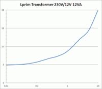
- Inductance versus voltage
See below the variation over the usable voltage range of a LCR meter (20 mV - 20V). At rated voltage the inductance increases to about 25 H.
If you manage to keep the flux (voltage per winding) constant between primary and secondary measurement, you get the expected inductance ratio.


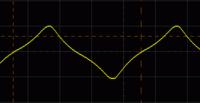
- distorted magnetizing current due to nonlinear core characteristics. The third harmonic has a magnitude of about 20% of fundamental in this case.

Although the waveform looks like "far from sinusoidal" (post #13), the effect on the total RMS current is quite low (about 2%), so a determination of current phase angle by magnitude measurements (post #12) still works quite good.


So what tell the measurements about significance of real input current?
At any rate, for a typical, non-defective, transformer the main component of the winding impedance is the reactance. The real part of the impedance is so small (relative to the reactance) as to have negligible effect in determining the exciting current.

You can view at it from two sides. Phase angle of impedance is about 74 degree. You can see it as a significant loss term (cos φ ≈ 0.27), or as nearly pure reactant current (sin φ ≈ 0.96).
 

Status
Not open for further replies.

Part and Inventory Search

Welcome to EDABoard.com

Sponsor

Back
Top