Continue to Site

Welcome to EDAboard.com

Welcome to our site! EDAboard.com is an international Electronics Discussion Forum focused on EDA software, circuits, schematics, books, theory, papers, asic, pld, 8051, DSP, Network, RF, Analog Design, PCB, Service Manuals... and a whole lot more! To participate you need to register. Registration is free. Click here to register now.

TIP31 feeding about 25 leds (audiorhytm circuit)

Status
Not open for further replies.
The Chinese amplifier has 4 volume controls: Volume, Bass Vol, Tre and Tre Vol. I do not know what Tre does.
You can connect a cable to the Bass Vol control to feed the LED circuit.

If the amplifier uses genuine Texas Instruments amplifier ICs then it will give 30W into 4 ohms for the left and right outputs and give 60W into 2 ohms for the bass output. Its spec's say 50W/4 ohms and 100W/2 ohms with horrible 10% distortion.
 

PLEASE refer back to the advice given earlier. By buying the Bluetooth module you have already spent more than it would cost to do the job properly - and you still haven't solved your problem.

The objectives are:

1. It should work on the audio signal, not the loudspeaker volume. This lets it work without shaking the house down to get enough brightness.
2. It must draw almost no power from the audio signal. Adding it shouldn't load or distort the sound you hear through the loudspeaker.
3. The LEDs should be on or off, not at individually different brightness or dim when the volume is low.
4. It should only respond to bass notes.

As I have already explained, you need a low pass filter to 'block' mid and high notes, a comparator to set the volume threshold that turns the LEDs on and off and a single transistor switch to sink the current from the LEDs. It is very simple to achieve all your needs, I estimate about 15 components and a total cost of just a few $$$.

Brian.

Thanks, I appreciate your advice's, I think its not too bad that board, I will need to solder some cables if planning to add extra features like the rca inputs, and locate where to take signals, maybe no need for adding extra amps for dedicated exciting stage for led driver, at least its bluetooth already by doing nothing, and the price was unbeatable, next time I will see how convenient is buying a board which has no bluetooth but I can added separately, I will do at least 3 speaker boxes so this is first try, then after concluded some things and learning more, will do better.

I am drawing my design using sketchup, yesterday made good final movements with my design, so far the conclusion is to make 2 led groups of 18 10mm leds, so my box will have 36 leds total, the reason I will do 2 groups, its because I concluded that group A will blink with bass pattern, and group B, I still don't know if with mediums or trebles, for now I dont think I will add 3 channel for 3 led groups, although its not bad idea. oh and thats right, I will need some crossovers, will later make some research about them, active and passive ones.

The Chinese amplifier has 4 volume controls: Volume, Bass Vol, Tre and Tre Vol. I do not know what Tre does.
You can connect a cable to the Bass Vol control to feed the LED circuit.

If the amplifier uses genuine Texas Instruments amplifier ICs then it will give 30W into 4 ohms for the left and right outputs and give 60W into 2 ohms for the bass output. Its spec's say 50W/4 ohms and 100W/2 ohms with horrible 10% distortion.

I was worried about the 5.25" pyle mid range speakers, I was doubting they can perform well at 50w, it would be still ok if amp throws 30W instead, and talking about the subwoofer driver, which is double coil 2ohm x 2, so it seems like I am going to need to put it at 2ohms instead of 4ohm? Once I have the amplifier, will see how many amps it draws, I bought a 24V 8.5A power supply, surely will be more than enough hehe, what a very cheap thing, and has a preset so I can vary they voltage. Another question, do you think it would be ok feeding that board with the 24V? or better going with 22v?

- - - Updated - - -

130727d1468551631-34q5hqp%5B1%5D.jpg


I am just done making some tests with this circuit, I observed how transistor went excited just by the output mini jack of my samsung cell phone, however the leds are not as bright as when they are directly connected to the power source (no transistor, just leds directly to power source), they are three 3.2 volts in series with a 120 ohm resistor, voltage source is about 12.5, more than enough, that put me to think if transistor steals some voltage and I ended with a little drop? if thats the case, then it seems like I should reduce the resistor, because maybe its like transistor ate some voltage?
 

The subwoofer speaker probably has its power rated with both 2 ohm voice coils operating. If only one voice coil is used then the power rating is probably half. Then you should connect the voice coils in series for 4 ohms and the amplifier and speaker will be happier with less current.
The cheap amplifier probably has built-in crossovers between the bass output and the stereo outputs. But the filters are probably simple, maybe too simple.

The maximum output before severe distortion is 30W for the bass (since the impedance is wrong) and 30W for each stereo channel for a maximum of 90W that will not occur for long durations. The class-D amplifiers are efficient so it might heat with 15W then the total of 105W divided by the 24V supply equals a current of 4.375A. If your "very cheap" power supply meets its power rating then it will be fine. But the power supply will probably cause odd sounds in the audio.
 

I see, so its not convenient wiring the subwoofer on 2 ohms? which means the two coils in parallel?

Now my big doubt is about that tip31 schematic that I showed previously, it seems like its not valid just calculating the resistor of the leds without considering what tip31 will take from there, is that the reason my leds are less brighter because they actually are not receiving 12v? will try to measure, will generate some flat noise, so it would be easy to read, but anyway let me know what about that please. Thanks.

Update: It was not necessary reading the voltage, I played a continuous sound generated by a sound generator, and saw how the leds are brightening a lot, just as directly connected to power source, that means that would be recommended adding a little transistor before the tip31 to completely excite it, thing that is weak with the regular music I played and leds never get fully brightening, so there is a space/tolerance where a little push would be recommended.

Update2: Hell yeah! I found this on google images!

130847d1468991771-oywxs.png
 

Attachments

  • OYWXS.png
    OYWXS.png
    17.1 KB · Views: 115
Last edited:

I fear that following another 10 year olds design will not do what you expect. The schematics you show are not 'designed' to work, they are someone's attempts at experiments that "did something", very inefficiently and were published. All of us more experienced members will tell you not to trust everything you find on the internet, most of it is nonsense and sometimes very dangerous.

If you use that circuit, it needs twice the input signal to light the LEDs and there is a strong possibility of the LEDs being damaged.

You would do far better to try understanding the problem and possible solutions than "Hell yeah! I found this on google images!" and be aware that your plans for mid and high frequency variations are not possible with that design.

Brian.

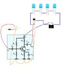
Are not the bases isolated one from each other? Please explain me, so I can learn, it made sense for me that small one requiere less in order to switch. I also found this schematic. (dont judge the missing resistors on the leds, I always add the recommended resistors)
 

Attachments

  • FGIJ4A3H7997XJO.LARGE.jpg
    FGIJ4A3H7997XJO.LARGE.jpg
    44.2 KB · Views: 79

The schematic in post #46 is a (if the values are correct) class A small signal amplifier and the design is fine. It is the sort of circuit you might use as a pre-amplifier to boost the sensitivity of a microphone or a low level audio signal to the level a main amplifier might need. In your application is isn't suitable though, you want a circuit that abruptly changes from off to on when a defined signal voltage is present and can produce enough current to fully saturate (make as conductive as posible) the TIP31. There are other reasons it wouldn't work too, for example it can only handle small signals and yours are already amplified and also it wouldn't produce enough current to bias the TIP31 enough.


Sorry about the quality, it isn't easy to photograph a sketch on a mobile phone while on a moving train! I certainly can't prototype it to check it!

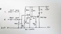
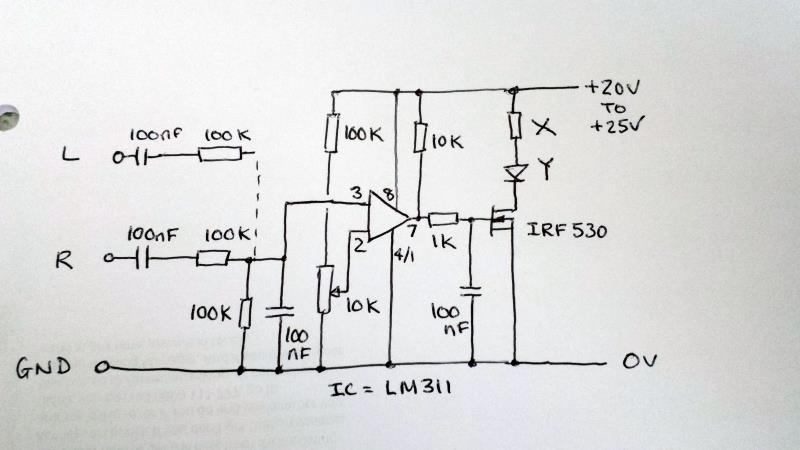
I made it as simple as possible and it certainly isn't optimal but it should work. The "L" input resistor and capacitor are only needed if you want to feed it from left and right channels, if you are only using one channel, leave them out. It is crudely filtered to make it respond only to low notes and it has a simple 'hold' circuit so the LEDs don't flash too quickly. The variable resistor sets the level (volume) at which the LEDs turn on.

Important: "Y" is your LED/LEDs and "X" is the resistor(s) in series with them. Use the calculation I gave earlier to find the resisitor values.

Pins 1 and 4 of the LM311 should both be wired to ground. If you try it and find the control is too sensitive, try adding another resistor of 390K between pin 3 and pin 8 of the LM311.

Brian.
 

Attachments

  • 20160720_114159a.jpg
    20160720_114159a.jpg
    45.4 KB · Views: 75

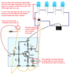
The circuit you drew has nothing to limit the current in the LEDs so they will instantly burn out. They also might not light. The TIP31 transistor also might burn out. The new circuit you found says it is for LED strips that already have series resistors to limit the current which is why they are designed for 12V.

Your circuit has some errors like too many LEDs in series (four 3.4V LEDs need 13.6V plus a few volts for the current-limiting resistor) that I explain. Use three LEDs in series and a resistor for a 12V power supply.

You said that the subwoofer speaker has "double coil 2ohm x 2". Are you connecting two of these subwoofer speakers?? Each speaker will have two 2 ohms coils.
Then when both coils are connected the speaker can be driven with a maximum allowed power of 100W but if one voice coil is used then the maximum allowed power might be 50W.
Now you said you might connect the two coils in parallel? Then you must learn that two 2 ohm coils in parallel make a load of 1 ohm that might destroy the amplifier!
The speaker has the wrong impedances for this amplifier so you should connect both coils in series which makes 4 ohms then the speaker and amplifier will not burn out but the output power will be about 30W instead of 60W.

You do not understand that a transistor has a current gain spec listed on its datasheet. The TIP31 collector current is 3A when its base current is 300mA for some transistors down to a base current of 60mA for others.
If your collector current is only 200mA then the current gain might be 150 so its base current needs to be 200mA/150= 1.3mA but might be much more since the current gain is a range of numbers.
So if the current gain of your TIP31 is 150 and the LEDs draw 200mA to be bright then the base current must be 1.3mA. If you feed the base less than 1.3mA then the LED current will be less and they will look dimmer. You do not know how much current your cell phone and signal generator produce and you do not know the actual current gain of the transistor you have so you are just guessing that the transistor is being turned on enough.

You show a 12V battery but where will it come from since the amplifier will use a 24V power supply?
 

Attachments

  • TIP31 with LEDs.png
    TIP31 with LEDs.png
    219.5 KB · Views: 79

The schematic in post #46 is a (if the values are correct) class A small signal amplifier and the design is fine. It is the sort of circuit you might use as a pre-amplifier to boost the sensitivity of a microphone or a low level audio signal to the level a main amplifier might need. In your application is isn't suitable though, you want a circuit that abruptly changes from off to on when a defined signal voltage is present and can produce enough current to fully saturate (make as conductive as posible) the TIP31. There are other reasons it wouldn't work too, for example it can only handle small signals and yours are already amplified and also it wouldn't produce enough current to bias the TIP31 enough.


Sorry about the quality, it isn't easy to photograph a sketch on a mobile phone while on a moving train! I certainly can't prototype it to check it!

I made it as simple as possible and it certainly isn't optimal but it should work. The "L" input resistor and capacitor are only needed if you want to feed it from left and right channels, if you are only using one channel, leave them out. It is crudely filtered to make it respond only to low notes and it has a simple 'hold' circuit so the LEDs don't flash too quickly. The variable resistor sets the level (volume) at which the LEDs turn on.

Important: "Y" is your LED/LEDs and "X" is the resistor(s) in series with them. Use the calculation I gave earlier to find the resisitor values.

Pins 1 and 4 of the LM311 should both be wired to ground. If you try it and find the control is too sensitive, try adding another resistor of 390K between pin 3 and pin 8 of the LM311.

Brian.

Clap clap clap! thanks friend, no doubt you have gave me something interesting to try, will include this in the protoboard practices. I don't think I want the hold option, I think I will be ok with just filtering the desire frequencies.

The circuit you drew has nothing to limit the current in the LEDs so they will instantly burn out. They also might not light. The TIP31 transistor also might burn out. The new circuit you found says it is for LED strips that already have series resistors to limit the current which is why they are designed for 12V.

Your circuit has some errors like too many LEDs in series (four 3.4V LEDs need 13.6V plus a few volts for the current-limiting resistor) that I explain. Use three LEDs in series and a resistor for a 12V power supply.

You said that the subwoofer speaker has "double coil 2ohm x 2". Are you connecting two of these subwoofer speakers?? Each speaker will have two 2 ohms coils.
Then when both coils are connected the speaker can be driven with a maximum allowed power of 100W but if one voice coil is used then the maximum allowed power might be 50W.
Now you said you might connect the two coils in parallel? Then you must learn that two 2 ohm coils in parallel make a load of 1 ohm that might destroy the amplifier!
The speaker has the wrong impedances for this amplifier so you should connect both coils in series which makes 4 ohms then the speaker and amplifier will not burn out but the output power will be about 30W instead of 60W.

You do not understand that a transistor has a current gain spec listed on its datasheet. The TIP31 collector current is 3A when its base current is 300mA for some transistors down to a base current of 60mA for others.
If your collector current is only 200mA then the current gain might be 150 so its base current needs to be 200mA/150= 1.3mA but might be much more since the current gain is a range of numbers.
So if the current gain of your TIP31 is 150 and the LEDs draw 200mA to be bright then the base current must be 1.3mA. If you feed the base less than 1.3mA then the LED current will be less and they will look dimmer. You do not know how much current your cell phone and signal generator produce and you do not know the actual current gain of the transistor you have so you are just guessing that the transistor is being turned on enough.

You show a 12V battery but where will it come from since the amplifier will use a 24V power supply?

Yes I knew it, I was thinking wrong at the time, certainly it would be 1ohm on that configuration, then my only suitable option is 4ohm, which is not bad. Please ignore those factors, leds without resistors or voltage sources, its like I obviously will calculate the resistors adnd modified whatever need to be adjusted to a different value showed there.

Omg! Are you telling me that thing will actually output about 30W at the subwoofer line? it surprised me considering I was expecting at least three times that value, I hope you are wrong and that thing pushes hard my driver with enough watts quantity (hope more than 30w), although I am not expecting something extremely powerful coming from that amplifier, that was also the reason I did want to buy a better driver with more specs, which does not mean that this driver wont be able to shake the entire house, I have a 3.5/4" subwoofer that came with a lantec desktop computer speakers, and that thing pushes really hard my room, comparing that subwoofer driver with the 8" pyle, the pyle its a monstrosity and feel good built, heavy and reinforced as hell, probably I will be happy with its performance. The little one is pushed with about 20w.

Hope to post soon, thanks everybody.
 
Last edited:

My power numbers are assuming that the Chinese amplifier uses genuine Texas Instruments power amplifier ICs and not a cheap Chinese copy that does not work well. Look at the TI datasheet to see the power numbers. The subwoofer amplifier might be the circuit that produces 100W into 2 ohms with horrible 10% clipping distortion. When the volume is turned down to avoid clipping then the datasheet shows about 60W into 2 ohms which is 30W into 4 ohms. It might be loud enough since double the power is only a little louder, 10 times the power sounds twice as loud.
 
The schematic in post #46 is a (if the values are correct) class A small signal amplifier and the design is fine. It is the sort of circuit you might use as a pre-amplifier to boost the sensitivity of a microphone or a low level audio signal to the level a main amplifier might need. In your application is isn't suitable though, you want a circuit that abruptly changes from off to on when a defined signal voltage is present and can produce enough current to fully saturate (make as conductive as posible) the TIP31. There are other reasons it wouldn't work too, for example it can only handle small signals and yours are already amplified and also it wouldn't produce enough current to bias the TIP31 enough.


Sorry about the quality, it isn't easy to photograph a sketch on a mobile phone while on a moving train! I certainly can't prototype it to check it!

I made it as simple as possible and it certainly isn't optimal but it should work. The "L" input resistor and capacitor are only needed if you want to feed it from left and right channels, if you are only using one channel, leave them out. It is crudely filtered to make it respond only to low notes and it has a simple 'hold' circuit so the LEDs don't flash too quickly. The variable resistor sets the level (volume) at which the LEDs turn on.

Important: "Y" is your LED/LEDs and "X" is the resistor(s) in series with them. Use the calculation I gave earlier to find the resisitor values.

Pins 1 and 4 of the LM311 should both be wired to ground. If you try it and find the control is too sensitive, try adding another resistor of 390K between pin 3 and pin 8 of the LM311.

Brian.

I could not figure out how the opamp gain is stabilized- there is no feedback loop connecting from the output. In the present config, the output will violently oscillate between 20V and 0.
 

My power numbers are assuming that the Chinese amplifier uses genuine Texas Instruments power amplifier ICs and not a cheap Chinese copy that does not work well. Look at the TI datasheet to see the power numbers. The subwoofer amplifier might be the circuit that produces 100W into 2 ohms with horrible 10% clipping distortion. When the volume is turned down to avoid clipping then the datasheet shows about 60W into 2 ohms which is 30W into 4 ohms. It might be loud enough since double the power is only a little louder, 10 times the power sounds twice as loud.

Yeah, :O data sheet talks by itself, 100w only on bridge mode and on 2ohms assuming some little distortion of 10%, I think still good for subwoofer driver, however the power that this thing is supposed to drive on 4ohms and assuming the right voltage input, probably will meet all my needs, and if we assimilate that, I think I actually did good buying an 8" quality subwoofer driver from cheap brand, because it will not be pushed by an enormous power, I am eager to see that pyle performing on those 30W, the enclosure its going to be "ported" which are more loud and efficient than sealed, convenient for this little project. I have observed some pyle reviews, there are lot of people happy with it, however it also has bad reviews, I think from people to tried to feed it with the labeled power rated, which never's correct, just peaks and fakes, I am actually happy giving a try to something good looks and the price is unbeatable, i am also practicing with a 15" boss subwoofer, just need to get the right amplifier, but thats will be next.
 

I could not figure out how the opamp gain is stabilized- there is no feedback loop connecting from the output. In the present config, the output will violently oscillate between 20V and 0.

LM311 is a comparator, not an op-amp. I agree performance would be improved by adding hysteresis but as I pointed out, it is stripped of all but essential parts to keep it simple.
The intention is to allow the threshold to be set so it can trigger on small voltages such as low audio levels. The input series resistor and shunt capacitor will to some degree reduce it's sensitivity to higher frequencies, it really needs an active filter but again it increases complexity. It should switch from 0V to 20V, that's how it ensures the MOSFET is fully switched.

Johanx2, the 'hold' is needed because otherwise it will respond to each cycle of the audio. That means if say a bass note at 100Hz is fed to it, the LEDs would flash 100 times a second. Your eyes can't see flashes faster than about 50 times per second! It is only three components and it will slow down the rate the LEDs turn on and off so the flicker is reduced. It really should be a little more complex if you want good results but try it first and see how you get on.

Note that it can be fed from 'line out' (pre-amp out) or from the loudspeaker wires because it places only a tiny load on the signal.

Brian.
 

A question friend, you mentioned you added a simple low filter, what components should I remove/change to make it able for mid or even high frequencies? I mentioned before that I will do 2 led groups, first one for bass, and seconds for mids, not sure if a third group for highs. I am happy with your design and surely will use it, that IRF530 drives a lot more than tip31, and still a very cheap component, specially in bulks. Are those 100K and the 100nf capacitor connected parallel at the input the low pass filter? I am eager to see how to modified it for mids and highs.

5907053400_1469011638.jpg
 

I am eager to see how to modified it for mids and highs.

But how you are going to see that? You cannot visually make out whether a LED is flickering at greater than 10Hz?

If you can focus it on the wall and rotate the LED (so that the spot traces out a line on the wall) then perhaps you can see high frequency flickers.

- - - Updated - - -

LM311 is a comparator, not an op-amp.

In this world, you have to run a lot just to stay at the same place. Can't we use a Schmitt trigger (no pun intended) based comparator?
 

But how you are going to see that? You cannot visually make out whether a LED is flickering at greater than 10Hz?

Well but think about what would happen with this beat pattern where _ is a bass hit of 1 second, and * is a high that came from a drum disc: _ * _ * _ , I am still not sure if I am confused, but with the low filter I only will see _ _ _ _, so is not it make sense to think that can add a high filter to second led group in order to only see them on when * * *, it would be interesting not only adding lights for bass, but also for highs, which obviously we only will see a clean light pattern where there are not too much instruments/noise.

I also thought that what betwixt did was to add a simple op amp before the mosfet, but damn! this is a marvel, can even be connected directly into the speaker terminals, which can be so convenient, clap clap clap, yes sr.
 
Last edited:

I wish the cheap Chinese amplifier system has an detailed English owners manual with all the spec's we need, a schematic and a parts list.
Does the bass amplifier already have a lowpass filter? Do the stereo amplifiers already have highpass filters? Are the filters simple or are they good? What is the level feeding the volume controls?

The comparator circuit was designed to detect all low level signals but maybe it can be adjusted to switch the LEDs suddenly on when it detects bass or drum beats that are high level. But all the LED audio circuits I have seen do not suddenly switch the LEDs on and off, instead they are linear so loud signals cause the LEDs to be bright and less loud signals cause the LEDs to be less bright.

It is simple to look at lowpass filter, bandpass filter and highpass filter in Google. A series resistor feeding a capacitor to ground is a very simple lowpass filter with a gradual slope. A series capacitor feeding a resistor to ground is a very simple highpass filter. There are many bandpass filter circuits available and some are just a lowpass filter and a highpass filter.
 

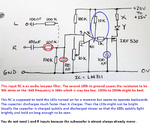
So whats going on here? I think that red circle is the low pass filter, although I may be wrong and some there is to set impedance? whats obvious for me is that 100nf (green circle) being the pulse holder?

130906d1469103041-345fg.jpg


I wish the cheap Chinese amplifier system has an detailed English owners manual with all the spec's we need, a schematic and a parts list.
Does the bass amplifier already have a lowpass filter? Do the stereo amplifiers already have highpass filters? Are the filters simple or are they good? What is the level feeding the volume controls?

The comparator circuit was designed to detect all low level signals but maybe it can be adjusted to switch the LEDs suddenly on when it detects bass or drum beats that are high level. But all the LED audio circuits I have seen do not suddenly switch the LEDs on and off, instead they are linear so loud signals cause the LEDs to be bright and less loud signals cause the LEDs to be less bright.

It is simple to look at lowpass filter, bandpass filter and highpass filter in Google. A series resistor feeding a capacitor to ground is a very simple lowpass filter with a gradual slope. A series capacitor feeding a resistor to ground is a very simple highpass filter. There are many bandpass filter circuits available and some are just a lowpass filter and a highpass filter.

Circuit board has not arrived, it will soon, maybe tomorrow, thanks for the filters data, I am taking a look.
 

Attachments

  • 345fg.jpg
    345fg.jpg
    87.1 KB · Views: 95

Red and green are both correct.

The first capacitor is primarily to ensure no residual voltage reaches the comparator, often amplifier outputs have a small DC 'background' voltage with the signal superimposed on it. The comparator would treat the residual as though it was audio and falsely trigger the LEDs. The resistor and capacitor in parallel form the low pass filter, the resistors main purpose is to keep pin 3 'tied' to a known voltage, in this case ground, although it also provides a discharge path for the capacitor. To explain why it works as a filter: a capacitor has a property called 'reactance' (symbol Xc) which is akin to it's resistance to an AC voltage. Unlike a resistor which keeps its value constant, the reactance drops as the frequency increases. So the series resistor and the capacitor to ground work as a voltage divider and as the capacitor is in the lower half, the voltage is divided (=made smaller) more at high frequencies than low ones. The low notes slip through, the high ones get reduced.

The capacitor circled in green is to 'hold' or slow down the LED reaction to the signal. It works like this: the LM311 has whats called an 'open collector' output, it doesn't produce any voltage at all but it can sink an externally provided voltage to ground. When the 'sink' is off, the capacitor charges through the 10K and 1K resistors and when the voltage has reached about 5V, the transistor turns on and the LEDs light up. When the 'sink' is active, pin 7 goes to almost ground and the capacitor discharges through the 1K resistor. At voltages below about 5V, the LEDs turn off again. It is a very crude way of stretching the pulse width so you don't see the LEDs flickering very fast.

The problem with the simple filter is it has a slow 'roll off', the higher notes are reduced but not as fast as would be ideal. It means a loud high note can still slip through if there was still enough of it left over after leaving the filter. It also isn't easily adaptable to work on other frequency ranges. To make stronger distinction between bands of frequencies you really need to use 'active' filters, ones that not only reduce the passage of the tones but create and add opposite tones to cancel the original. You would be looking at needing at least one more stage before the comparator with an IC and some more resistors and capacitors. Normally, if we need filters with rapid 'roll off' we chain several filters together but I would estimate for your needs a single filter stage would be adequate. If you used three filters, you could for example make the low pass filter block anything above say 200Hz, the bandpass filter block less then 200Hz and greater than 3KHz and the high pass filter block anything below 3KHz.

Audioguru's points are noted but as I said, it was designed on a scrap of paper on board a train and sent by mobile phone so I had to guess some of the values. Given the slow roll off of the filter I think it would still be OK but I agree, if an active filter was used, 200Hz would be a better cut-off frequency to aim for. The 'hold' is difficult to reverse without adding extra components because the outputof the LM311 is fixed by it's design. It would be better if the on to off ratio worked the other way around but it should work to some degree as it is.

Brian.
 

Status
Not open for further replies.

Part and Inventory Search

Welcome to EDABoard.com

Sponsor

Back
Top