Continue to Site

Welcome to EDAboard.com

Welcome to our site! EDAboard.com is an international Electronics Discussion Forum focused on EDA software, circuits, schematics, books, theory, papers, asic, pld, 8051, DSP, Network, RF, Analog Design, PCB, Service Manuals... and a whole lot more! To participate you need to register. Registration is free. Click here to register now.

Sinewave inverter prototype...

Status
Not open for further replies.
Hi DeepOne!
Can I use IR2109 for irf3205 or 75n75 for low frequency 50hz transfor as this is the only gate driver available in local shop.
My Other is that I want to use Current sensing on the out put rather than on the sources of the transformer Now can I use the same firmware for this purpose because you are using Comparator and ADC both.
 

Hello, Naseerak.
Yes, You can. But if You want to use current sensing on the output stage, please do it by himself because in this moment it is not interesting for me.
 

But why r u using ADC and comparator at the same time?

- - - Updated - - -

And if I want to do it on the sources what should be the accuracy of the shunts. and what yourself you using for shunt.
 

Comparator for short circuit protection, ADC for measuring. Implementing more accuracy in shunt simple give more accuracy in result, but it is not essential for this inverter.
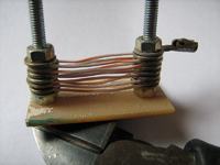
As shunt resistor usually i use something like that -
 

Well I am thinking of using PCb fuses to be used for shunt... any thoughts from you?
 

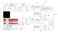
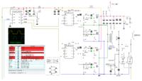
Whats the difference between the two scheme..
also tell me do you have HV version of tin13 based inverter 350v DC to 220v AC
 

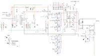
Difference in used driver chips - ir2304 versus ir2109. And i have no 350VDC version, moreover this schemes is not tested in hardware.
________________________________________
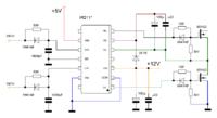
scheme of ir211* to ir2304 equivalent. But ir211* is much more moody chip than 2304.
 
Last edited:

With a little modification in hardware this attiny13 version can be adapted to HV version?

- - - Updated - - -

As for IR2110 is concerned it is widely available here a 1$. and the dead time can be implemented in firmware by putting some blank entries in the tables at the start and end depending on the timer interrupt value.
 

for this needs dead-time delay 1,2 - 1,5uS in drivers, as minimum.

As there is only a single table the dead time can be easily be implemented by putting some 0,s in the table at the end and beginning.
 

for me is better to use cheap STM8S mcu with onboard 3 complementary outputs and dead-time insertion, instead of thinking up about software dead time generation on old Atmel mcu's.
 

Hi DeepOne!
I could,nt understand this topology If this is Push-pull then why you are using 4 signal from micro-controller.
 

Hi, Naseerak.
generally it is sligtly modified push-pull topology.
why you are using 4 signal from micro-controller.
for me is curiously enough as this will work )

______________________________________________________
 
Last edited:

Status
Not open for further replies.

Similar threads

Part and Inventory Search

Welcome to EDABoard.com

Sponsor

Back
Top