danny davis
Banned
The ripples frequency is either 50hz or 60hz?
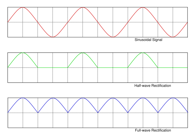
Ripple on a full wave rectified supply is 2x the mains frequency
Full wave rectified supply 60hz X 2 = ripple frequency is 120hz?
Ripple on a full wave rectified supply is 2x the mains frequency
Full wave rectified supply 60hz X 2 = ripple frequency is 120hz?