Continue to Site

Welcome to EDAboard.com

Welcome to our site! EDAboard.com is an international Electronics Discussion Forum focused on EDA software, circuits, schematics, books, theory, papers, asic, pld, 8051, DSP, Network, RF, Analog Design, PCB, Service Manuals... and a whole lot more! To participate you need to register. Registration is free. Click here to register now.

[SOLVED] Positive or Negative going Pulses or Edges

Status
Not open for further replies.
So when you ADD an inverter, you ADD the HIGH states pulse width? this will equal the inverters delay time
You do not make any sense.
An inverter inverts THE ENTIRE pulse period, not just the positive pulse. If you have a logic IC that is clocked on the positive-going edge and you invert the clock then this logic IC must wait until the positive-going edge (which was the negative-going edge before the pulse period was inverted) occurs. Then the delay time is the pulse width.

Why will it mess up the logic? they use them in a circuit at work
I do not know what they use at your work.
If all the other logic is clocked on the positive-going edge but this logic IC has an inverter to delay its clocking a pulse width later then it is clocked AT THE WRONG TIME!

But you do not understand any of this stuff and I do not know why you are asking about it.
If you looked at the datasheets then maybe you will find that all the logic is clocked on a positive-going edge EXCEPT one IC that is clocked on the negative-going edge. Then it has an inverted clock so that it is clocked at the same time as all the other ICs. UNDERSTAND?

Yes I know The positive edge is 20 microseconds late or delayed from the Non inverted clock
I think you are talking about when the clock is inverted?

Positive edge going trigger , triggers EVENTS later than Negative edge going trigger
Negative Edge going triggers , triggers EVENTS BEFORE Positive edge going trigger IC chips
You make no sense. You do not understand ANYTHING about clocked logic.

You cannot say LATER unless you say the starting point:
1) If the starting point is the negative edge then the positive edge occurs later.
2) if the starting point is the positive edge then the negative edge occurs later.

NOTHING can occur before.
 

Yes true, the Inverter adds a time delay compared to the other clocked IC's , the SYNC is offset

The Time delay i'm not sure is a half of a clock , more or less

I'm guessing a half of a clock is half of the clock period? or half of the HIGH state?

Not sure why the time delay is half of a clock, because the inverter , inverters the clocks pulse period which is a whole clock not a half of a clock
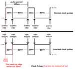
Here's how to understand it. Draw a picture of several cycles of the original clock, High for 20 usec., and Low for 80 usec. in each cycle. Immediately below that picture, draw a picture of the inversion of that first clock. Where the first clock is High, you now draw a Low, and where the first clock is Low, you now draw a High. These two pictures, one above the other, should be presented so that directly under each negative-going edge in first picture is a positive-going edge in the second picture. Now suppose that either one of these clocks might be connected so some input that is sensitive to positive-going edges. So get a red pen and mark all the positive-going edges in both pictures. Then compare them. You will see that the positive-going edges in the second picture are delayed from the positive-going edges in the first picture by 20 usec. This is not half a clock. This is not a whole clock. It is just 20 usec. That is how much delay you would be adding if you added an inverter to the clock. On the other hand, if the input is sensitive to negative-going edges, a similar analysis shows that the negative-going edges are delayed by 80 usec. Since that is the only part of the clock that the input circuit cares about, that is the delay that is seen by the input circuit if you add an inverter in that case.
 

I already gave him a picture like that on another of his thousands of threads. He doesn't understand these things.
 

Attachments

  • clock pulses 2.png
    clock pulses 2.png
    12.8 KB · Views: 100

You will see that the positive-going edges in the second picture are delayed from the positive-going edges in the first picture by 20 usec. This is not half a clock. This is not a whole clock. It is just 20 usec. That is how much delay you would be adding if you added an inverter to the clock.

This is one of my main points , is that the inverter adds a 20usec delay
AudioGuru just can't seem to figure that out or see it

What is this called when u do something like this? this type of delaying a clock

So get a red pen and mark all the positive-going edges in both pictures. Then compare them.

Mark all the positive going edges with RED
Mark all the Negating going edge with Blue

Don't add an inverter

This is my other main point i'm trying to make

From the Starting Point to a Positive Edge occurs at XXX time
From the Starting Point to a Negative Edge occurs at XXX time

My Point is that a Positive Going Edge occurs BEFORE a Negative Going Edge compared to a starting point

General Rule Of Thumb:
So this means that ALL negative going edge IC clocked chips will start after all the Positive going edge IC chips in a circuit
So the timing from the Negative going edge IC clocked chips will be OFFSET and DISPLACED from all the Positive going edge IC chips in a circuit

Aren't I right?
 

If you have a clocked circuit that works and it has more than one clocked IC and you want their outputs to be synchronized then YOU DO NOT add an inverter to one or two of their clock inputs because it will mess up the synchronization. Please forget about adding an inverter to invert the clock edges.

In a clock circuit, a negative edge occurs after a positive edge and a positive edge occurs after a negative edge. Nothing occurs BEFORE because maybe the clock didn't start running before.

Your General rule Of Thumb is WRONG: You cannot say that a clocked IC with one edge polarity starts first. It depends on which polarity the clock starts with.
 

add an inverter to one or two of their clock inputs because it will mess up the synchronization.

True I know , so why do designers do this than? i see it all the time in circuits

They mix negative going edges with positive going edge IC chips, this will mess up the synchronization

In a clock circuit, a negative edge occurs after a positive edge and a positive edge occurs after a negative edge. Nothing occurs BEFORE because maybe the clock didn't start running before.

Your General rule Of Thumb is WRONG: You cannot say that a clocked IC with one edge polarity starts first. It depends on which polarity the clock starts with.

True, because a clock is free running right?

You cannot say that a clocked IC with one edge polarity starts first. It depends on which polarity the clock starts with.

True, but ONE EDGE POLARITY will Occur before the other polarity which will mess up the synchronization if you mix positive and negative going edge IC clock chips right?

One polarity will occur before the other one
 

I will in time , everything in controlled docs at my work remember

but you know i'm right about the edges
 

You are completely confused about clock edges and clocked edges.

I'm not confused about it, because tunelabguy understands what i'm saying

Why do u think most circuits only have positive going edge IC chips?

They are mixed, with positive and negative going edge IC chips , or they use inverts to invert the clock signals

I will post the schematic soon since u don't believe me
 

Why do u think most circuits only have positive going edge IC chips?
I never said that. I look at datasheets to see which edge a counter IC is clocked with. Most Cmos counters are clocked on the positive-going edge.

The CD4017, CD4022, CD4026, CD4029, CD4040, CD4060 and more are clocked on the positive-going edge. The CD4020 and maybe others are clocked on the negative-going edge.
 

I'm not confused about it, because tunelabguy understands what i'm saying
Not really. Most of what you write is so imprecise that I can only respond to the few things you say that I do understand.

As for why designers might mix positive and negative edge chips in the same circuit, they do so because that's what their design calls for. It is not "messing up" to use an inverter in some places or to use chips with different edge sensitivity. It is messing up to take a circuit that works and change it by adding an inverter. If you don't understand how the circuit works, you are in no position to make that kind of change. The general observation that adding an inverter will mess things up is based on the assumption that the circuit works the way it is now. If you ever learn enough electronics to actually design a circuit, then you will see what it needed to make something work. For now, it is best if you just assume that the circuit works by magic, and if you change anything like add an inverter, or change a chip from positive edge to negative edge sensitive, you will break the magic spell and it won't work anymore.
 
Last edited:

Status
Not open for further replies.

Part and Inventory Search

Welcome to EDABoard.com

Sponsor

Back
Top