Continue to Site

Welcome to EDAboard.com

Welcome to our site! EDAboard.com is an international Electronics Discussion Forum focused on EDA software, circuits, schematics, books, theory, papers, asic, pld, 8051, DSP, Network, RF, Analog Design, PCB, Service Manuals... and a whole lot more! To participate you need to register. Registration is free. Click here to register now.

[SOLVED] Positive or Negative going Pulses or Edges

Status
Not open for further replies.
Danny you seem to forget that a time period has to have a starting point. FROM THE SAME REFERENCE STARTING POINT, a circuit operated by say a falling edge may not see that edge for a little longer if the signal is inverted. It's the edge, (the change of level) that matters so if the signal is inverted it will be at the other end of the pulse and hence have a different delay FROM THE REFERENCE POINT.

Brian.
 

What u mean by the logic being clocked a half cycle late? how so?
If the clock pulse is high for 80us and low for 20us and the clocked logic is clocked by a positive-going edge then you invert the clock:
1) When the positive-going edge occurs then it is inverted to a negative edge so the logic waits. It is late.
2) When the negative-going edge occurs 80us later it is inverted to a positive edge so the logic does what it was supposed to do earlier, but it happens 80us too late.

What did i do wrong?
Your mixed-up language was not proper English.
An edge has no time. Instead it has a time delay from another edge.
For the clock signal that is not inverted:
1) The leading edge is not at 80us. Instead the negative edge is 80us later than the positive edge.
2) The negative edge is not 100us. Instead it is 100us later than the previous negative edge, or as above.
 
Last edited:

a time period has to have a starting point. FROM THE SAME REFERENCE STARTING POINT, a circuit operated by say a falling edge may not see that edge for a little longer if the signal is inverted. It's the edge, (the change of level) that matters so if the signal is inverted it will be at the other end of the pulse and hence have a different delay FROM THE REFERENCE POINT.

Can you please give me examples of what u mean?

If the clock pulse is high for 80us and low for 20us and the clocked logic is clocked by a positive-going edge then you invert the clock:
1) When the positive-going edge occurs then it is inverted to a negative edge so the logic waits. It is late.
2) When the negative-going edge occurs 80us later it is inverted to a positive edge so the logic does what it was supposed to do earlier, but it happens 80us too late.

Yes the inverter delays the clock signal a half a clock later , this is my main point , is the inverter doesn't just invert the clock signal but also it delays the clock also so this throws off the timing or OFFSETS the timing compared to the other circuit

What you're guys are saying is that it's not just the EDGE it's looking at but the change of level from low to high or high to low

- - - Updated - - -

EXAMPLE:
An edge has no time. Instead it has a time delay from another edge.

What do you mean by this? I thought the leading edge and the Falling Edge was what made the pulse width

For the clock signal that is not inverted:
1) The leading edge is not at 80us. Instead the negative edge is 80us [/b]later[/b] than the positive edge.
2) The negative edge is not 100us. Instead it is 100us later than the previous negative edge, or as above.

THIS IS WHAT THE OUTPUT OF THE CLOCK SIGNAL IS
Clock Period = 100 uSeconds
Clock logic HIGH Pulse width = 20 uSeconds
Clock Logic Low pulse width = 80 uSeconds

This is what I got for the clock that is NOT INVERTED:
Positive going edge will be Zero microseconds? the leading edge of the clocks pulse width
Negative going edge will be 20 microseconds? the falling edge of the clocks pulse width

Is this right or wrong?
 

Yes the inverter delays the clock signal a half a clock later
Or, you could say it advances the clock signal by half a clock. It is all the same thing for a periodic signal.
What you're guys are saying is that it's not just the EDGE it's looking at but the change of level from low to high or high to low
That's the same thing. And edge is a change of level from low to high or high to low.
What do you mean by this? I thought the leading edge and the Falling Edge was what made the pulse width
Yes, the pulse width is the time from one edge to the next edge. But what they were saying was that an edge itself, when considered all by itself, takes essentially no time at all, other than the very short rise or fall time due to the round off of the edges that we spoke of earlier. But that is generally just a fraction of a microsecond.
 

Can you please give me examples of what u mean?
A clock signal goes high then a little later it goes low then a little later it goes high again then a little later it goes low again over and over. The "little later" is a time delay.
If an IC is clocked by a positive edge and you invert the clock pulses then the clocked IC is clocked later than before. Why can't you understand the delay?

What you're guys are saying is that it's not just the EDGE it's looking at but the change of level from low to high or high to low
Why don't you understand that the edge IS the change of level???? The edges are vertical lines on a 'scope that shows the rectangular waveform.

(An edge has no time. Instead it has a time delay from another edge) What do you mean by this? I thought the leading edge and the Falling Edge was what made the pulse width
Why don't you understand that edges have no width??? An edge is at the beginning and at the end of a pulse. The pulse width is the time delay that happens between edges.

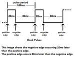
(Timing details of a clock pulse)
Positive going edge will be Zero microseconds? the leading edge of the clocks pulse width
Negative going edge will be 20 microseconds? the falling edge of the clocks pulse width

Is this right or wrong?
Your English is missing a few important words:
The pulse begins at Zero microseconds with the vertical edge.
The negative edge occurs 20 microseconds after the positive edge.
The positive edge occurs 80ms after the negative edge.

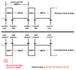
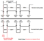
Look at my sketch of clock pulses:
 

Attachments

  • clock pulses.png
    clock pulses.png
    7.3 KB · Views: 113

If an IC is clocked by a positive edge and you invert the clock pulses then the clocked IC is clocked later than before. Why can't you understand the delay?

I already know that the Inverter IC chip delays the clocked IC later than before

Why don't you understand that edges have no width??? An edge is at the beginning and at the end of a pulse. The pulse width is the time delay that happens between edges.

Yes I know that

The pulse begins at Zero microseconds with the vertical edge.
The negative edge occurs 20 microseconds after the positive edge.
The positive edge occurs 80ms after the negative edge.

Yes the Positive edge OCCURS at the beginning which is at zero microseconds and it occurs again at 80mSec

when the CLOCK SIGNAL is INVERTED:

The Negative Edge OCCURS at 80 microSeconds
The Positive Edge Occurs at 100 microSeconds

When the Clock Signal is Not Inverted:

The Negative Edge Occurs at 20 microseconds
The Positive Edge Occurs at the beginning at 0 and again at 80 microseconds


The Points I'm trying to make is, when a circuit designer chooses to have an IC chip being Positive edge going , the timing is advanced a half of a clock before than using an IC chip that is negative edge going , because the
EDGES OCCUR at different TIMES
, which is a time delay

Plus when you Invert the Clock signal , this adds even more of a time delay plus the EDGE'S of the positive and negative edges OCCUR at different times because the HIGH state and Low state have been swapped which changes the EDGES to Occur at way different times

Yes I know that the EDGES aren't a TIME delay, but when measuring on a O-scope the positive and negative edges and what time they OCCUR at is what i'm talking about

What program did u do that clock pulse sketch on? so I can make one?

Try making on that is inverted and you will see when the positive and negative edges occur , they are way different times
 

Yes the Positive edge OCCURS at the beginning which is at zero microseconds and it occurs again at 80uSec
No it doesn't. It repeats every 100us.

when the CLOCK SIGNAL is INVERTED:

The Negative Edge OCCURS at 80 microSeconds
The Positive Edge Occurs at 100 microSeconds

When the Clock Signal is Not Inverted:

The Negative Edge Occurs at 20 microseconds
The Positive Edge Occurs at the beginning at 0 and again at 80 microseconds
No they don't. You understand the timing WRONG.
You must say where the timing begins from: The negative edge occurs 80us after the positive edge, and the positive edge occurs 20usafter the negative edge. The positive edge occurs 100us after the previous positive edge and the negative edge occurs 100us [/b]after the previous negative edge[/b].

The Points I'm trying to make is, when a circuit designer chooses to have an IC chip being Positive edge going , the timing is advanced a half of a clock before than using an IC chip that is negative edge going , because the , which is a time delay

Plus when you Invert the Clock signal , this adds even more of a time delay plus the EDGE'S of the positive and negative edges OCCUR at different times because the HIGH state and Low state have been swapped which changes the EDGES to Occur at way different times

Yes I know that the EDGES aren't a TIME delay, but when measuring on a O-scope the positive and negative edges and what time they OCCUR at is what i'm talking about
The circuit was designed using available ICs so that the circuit works properly.

What program did u do that clock pulse sketch on? so I can make one?
I sketched the clock pulses and make all my schematics with Microsoft Paint program.

Try making on that is inverted and you will see when the positive and negative edges occur , they are way different times
Of course, the timing is delayed.
 

I fixed it now

The Clock Time begins at zero

when the CLOCK SIGNAL is INVERTED:

The Negative Edge OCCURS at 100 microSeconds
The Positive Edge Occurs at 80 microSeconds

When the Clock Signal is Not Inverted:

The Negative Edge Occurs at 20 microseconds
The Positive Edge Occurs at the beginning at 0 and again at 100 microseconds
 

I fixed it now

The Clock Time begins at zero

when the CLOCK SIGNAL is INVERTED:

The Negative Edge OCCURS at 100 microSeconds
The Positive Edge Occurs at 80 microSeconds No it does not!

When the Clock Signal is Not Inverted:

The Negative Edge Occurs at 20 microseconds
The Positive Edge Occurs at the beginning at 0 and again at 100 microseconds
See, you got it WRONG again. Maybe you read backwards from right to left?
 

Attachments

  • clock pulses 2.png
    clock pulses 2.png
    12.8 KB · Views: 95

The inverter delays the Clock signal a half a clock?

A Half a clock means? one clock period ? or just the HIGH state?

How do u know the inverter delays the clock signal only half a clock signal and not a whole clock signal? or more?

Which Logic IC chips can have Unregulated VCC supply? how much ripple can Logic IC have on the supply , and what happens when there is to much Ripple on the VCC for Logic IC chips?
 

How do u know the inverter delays the clock signal only half a clock signal and not a whole clock signal? or more?
You can see it on an oscilloscope. it will look exactly like my sketch.

Which Logic IC chips can have Unregulated VCC supply? how much ripple can Logic IC have on the supply , and what happens when there is to much Ripple on the VCC for Logic IC chips?
Instead of asking millions of questions here, why don't you look at the answers on the datasheets?
 

Can TTL logic IC handle more ripple and unregulated VCC than CMOS logic IC?

What happens if you have to much ripple or the VCC is unregulated to much for TTL logic and CMOS logic IC chips?

So all logic IC chips , TTL gates and CMOS gates, delay a clock signal by half of a clock? I thought the delay was in Nanoseconds from input to output

An inverter delays the clock signal by half of a clock , but also an inverters output current is buffered? it outputs more current causes it's a current buffer also?
 

Can TTL logic IC handle more ripple and unregulated VCC than CMOS logic IC?
No, you got it backwards. Look on their datasheets.

What happens if you have to much ripple or the VCC is unregulated to much for TTL logic and CMOS logic IC chips?
What do you think happens?? The logic becomes WRONG!

So all logic IC chips , TTL gates and CMOS gates, delay a clock signal by half of a clock? I thought the delay was in Nanoseconds from input to output
Absolutely NOT!
Some chips invert and other chips don't invert. The delay is almost nothing and will not affect your low frequency circuits.

An inverter delays the clock signal by half of a clock , but also an inverters output current is buffered? it outputs more current causes it's a current buffer also?
A CD4069 hex inverter is NOT BUFFERED. Its output current is the same low amount as a buffered Cmos gate. Why don't you ever look at the datasheets?
 

The inverter delays the Clock signal a half a clock?
No, it does not. An inverter just inverts the signal. It changes Highs to Lows and Lows to Highs. It does not add any appreciable delay. It only looks like it adds a delay when the clock is a 50% duty cycle clock. That is because when you invert the signal, it looks exactly the same as if the original signal were delayed by half a clock. But for a clock that is not at 50% duty cycle, this is no longer true. If you invert the clock you have been talking about - the one that is High for 20 usec and Low for 80 usec., you do not get a delayed version of the original clock. You get a completely different looking clock - one that is High for 80 usec. and Low for 20 usec. No matter how you try to delay the original clock, it will never look like that. So it is not very helpful to think about inverters as adding a half-clock delay. It is sloppy thinking that will lead you astray. Inverters just invert. That is all. They do not add delay (not very much, anyway).
 

An inverter just inverts the signal. It changes Highs to Lows and Lows to Highs. It does not add any appreciable delay.
I mentioned a delay caused by inverting the clock to an IC because then this clocked IC will have outputs that are delayed from what they were before the inverter was added (the clocked IC must wait for the proper polarity clock edge). Then sync with other clocked ICs without the inverted clock will be way off.
 

I mentioned a delay caused by inverting the clock to an IC because then this clocked IC will have outputs that are delayed from what they were before the inverter was added (the clocked IC must wait for the proper polarity clock edge). Then sync with other clocked ICs without the inverted clock will be way off.

Yes true, the Inverter adds a time delay compared to the other clocked IC's , the SYNC is offset

The Time delay i'm not sure is a half of a clock , more or less

I'm guessing a half of a clock is half of the clock period? or half of the HIGH state?

Not sure why the time delay is half of a clock, because the inverter , inverters the clocks pulse period which is a whole clock not a half of a clock
 

You still completely miss the point. A negative edge means the edge when the level drops to a '0' and a positive edge is when it rises to a '1'. Whether it is a clock signal or not is completely irrelevant.

Please try to understand: If you are measuring a pulse, it's duration is the time delay between the first (leading) edge and the last (trailing) edge, regardless of whether the edges are negative going or positive going.
If it is a continuous signal or a clock, the PERIOD is the time between one edge and the next edge going in the same direction. It could be postive to positive or negative to negative but it has to be between two edges of the waveform going in the same direction. If you invert it, the same applies, it is still measured over one complete cycle, from one edge to the next identical edge.

Pulse width = time from leading edge to trailing edge
Period (1/f) = time from one edge to the next edge going in the same direction, one complete cycle.

Brian.
 

Pulse width = time from leading edge to trailing edge
Period (1/f) = time from one edge to the next edge going in the same direction, one complete cycle.

I understand this and know this

but what is the formula when you ADD an inverter? it adds how much delay time? or half of a clock ?

Ch1 is a Non Inverted clock signal
Ch2 is a Inverted clock signal

You will see the delay time compared to the non inverted clock signal because of the inverter

So what is the formula when you ADD the inverter in?
 

If you add an inverter then the delay time for clocking is the pulse width.
Look at my "clock pulses 2" sketch again. The clock clocks the logic on the positive-going edge and the pulse width is 20us. When the clock is inverted then the positive-going edge occurs 20us late.

But you and nobody else wants to add the inverter because it will mess up the logic.
 

Attachments

  • clock pulses 2.png
    clock pulses 2.png
    12.8 KB · Views: 75

If you add an inverter then the delay time for clocking is the pulse width.

So when you ADD an inverter, you ADD the HIGH states pulse width? this will equal the inverters delay time

But you and nobody else wants to add the inverter because it will mess up the logic.

Why will it mess up the logic? they use them in a circuit at work

Yes I know The positive edge is 20 microseconds late or delayed from the Non inverted clock

Positive edge going trigger , triggers EVENTS later than Negative edge going trigger

Negative Edge going triggers , triggers EVENTS BEFORE Positive edge going trigger IC chips
 

Status
Not open for further replies.

Part and Inventory Search

Welcome to EDABoard.com

Sponsor

Back
Top